
I have spent a significant part of my engineering career focused on the production of complex steel castings for rail transit applications. Among these, the subway axle box body is one of the most demanding components because it combines thin walls, multiple intersecting ribs, and several localized hot spots. The axle box body is a critical part of the subway bogie running gear. Its design structure is complex, and the requirements for both external appearance and internal quality are strict. Every functional region must achieve acceptable internal compactness. In my experience, the occurrence of casting defects in such components is not random; it is closely linked to the gating system, riser design, padding geometry, and local cooling practice. I have therefore analyzed the casting process for a specific subway axle box body, compared the original process with production reality, and optimized the method to reduce the proportion of casting defects. The final result was a scrap rate below 4%, which confirmed the effectiveness of the optimized approach.
The subway axle box body I examined is a symmetric component. Its material is ZG230-450 cast steel. The net mass of the casting is 45 kg. The maximum envelope dimensions are 700 mm by 350 mm by 170 mm. The main wall thickness is 16 mm. The design includes many rib intersections. This makes the part a thin-walled, multi-hot-spot box structure. The manufacturing and inspection of the axle box body must follow TB/T 2942.1-2020, which is the technical requirements and inspection standard for cast steel components for locomotives and rolling stock. Non-machined surfaces must be coated with primer and topcoat according to the drawings and technical requirements. Casting fillets are R3 to R5. The manufacturer name, manufacturing year and month, and serial number must be cast on the lower rib surface.
| Parameter | Value | Unit |
|---|---|---|
| Material | ZG230-450 | — |
| Net mass | 45 | kg |
| Maximum envelope | 700 × 350 × 170 | mm |
| Main wall thickness | 16 | mm |
| Casting fillet radius | R3–R5 | mm |
| Standard | TB/T 2942.1-2020 | — |
| Surface protection | Primer and topcoat | — |
| Marking | Manufacturer, year, month, serial number on lower rib | — |
To visualize the type of geometric complexity I am dealing with, consider a representative complex casting with intersecting walls and multiple hot spots.
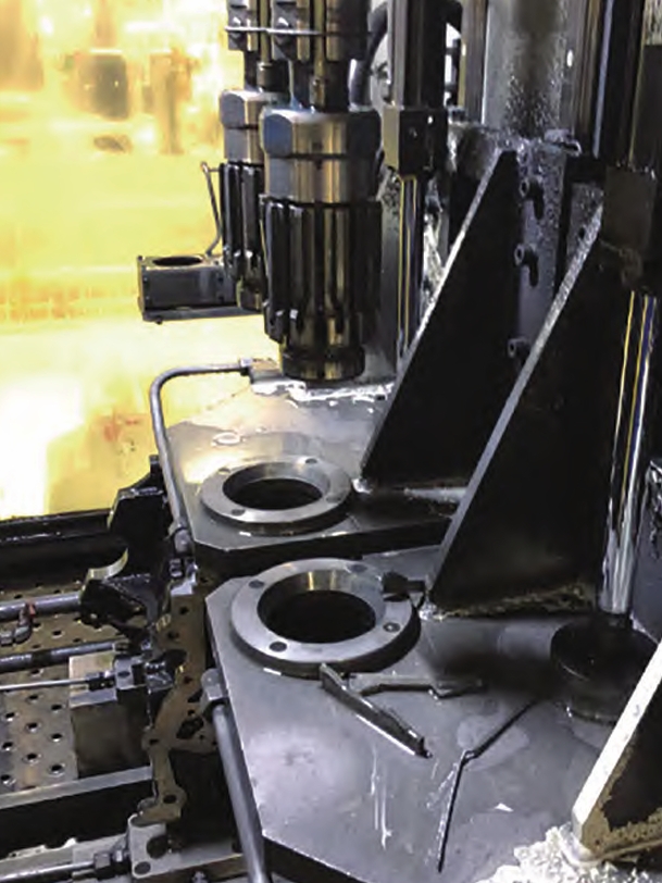
Although the image shows a different casting, the principles of feeding, gating, and thermal management are directly transferable to the axle box body. The presence of multiple hot spots means that casting defects such as shrinkage porosity, gas holes, and sand inclusions can easily form if the process is not precisely controlled. In my analysis, I focused on the shaft cylinder, the spring seats, and the rib intersections because these regions have the highest thermal modulus and the longest solidification time.
The original casting process used one mold with two pieces, arranged symmetrically. I used a middle pouring system. The ladle nozzle diameter was 50 mm. The sprue diameter was 60 mm. The runner cross-section was a trapezoid with dimensions 65 mm/60 mm by 30 mm. The ingate cross-section was a trapezoid with dimensions 45 mm/40 mm, height 30 mm, transitioning to 10 mm at the casting. Liquid steel entered from the axle rib plate position to reduce erosion of the sand mold. I placed sufficient modulus insulating and exothermic risers at the central shaft cylinder and at the top of both spring seats. At the same time, I designed a conformal padding in the central shaft cylinder with a curvature matching the waist-shaped riser. The padding depth was selected according to handbook recommendations. I placed chills and rivets at the small hot spots of each casting to work with the risers to ensure internal compactness and to avoid shrinkage holes and shrinkage porosity in local hot spots. The chills were cut from carbon steel plates. I used carbon dioxide hardened sodium silicate sand for molding and core making. In positions where rivets could not be placed, such as fillets and character locations, I used chromite sand for chilling. To better avoid sand holes and gas holes, I set 8 mm machining allowance on the top surface of the upper mold. For other machining positions, I selected 5 to 6 mm machining allowance according to handbook recommendations.
| Gating Parameter | Original Value | Unit |
|---|---|---|
| Molding layout | 1 mold, 2 pieces, symmetric | — |
| Gating type | Middle pouring | — |
| Ladle nozzle diameter | 50 | mm |
| Sprue diameter | 60 | mm |
| Runner section | Trapezoid 65/60 × 30 | mm |
| Ingate section | Trapezoid 45/40 × 30 to 10 | mm |
| Ingate location | Axle rib plate position | — |
| Feeding Parameter | Original Value | Unit |
|---|---|---|
| Riser type | Waist-shaped insulating risers | — |
| Riser number | 2 | — |
| Padding thickness | 15 | mm |
| Padding depth | 80 | mm |
| Chill material | Carbon steel plates | — |
| Local chilling | Rivets and chromite sand | — |
| Top machining allowance | 8 | mm |
| Other machining allowance | 5–6 | mm |
I observed three main categories of casting defects: gas holes on the inner surface of the shaft cylinder, shrinkage porosity in the shaft cylinder, and occasional sand holes. The gas holes were 3 to 5 mm in size. They were distributed in a diffuse manner. The shape was spherical or elliptical. The inner wall was smooth and dark. They were mostly located in the upper part of the casting. The closer to the top, the larger the gas hole defects. Based on visual characteristics, I classified these as entrained gas holes. The formation reason was that the gating system was not reasonably designed. The sprue cross-section was larger than the ladle nozzle diameter. During pouring, the liquid steel stream was not full. This easily entrained gas into the mold cavity. Because the casting wall was thin, the solidification speed was fast. Bubbles could not float out of the liquid steel in time, so they remained as entrained gas holes. I can describe the gas entrainment flow with a simple orifice equation: $$Q_{ent} = C_d A_n \sqrt{\frac{2 \Delta P}{\rho}}$$ where \(Q_{ent}\) is the entrained gas volumetric flow, \(C_d\) is the discharge coefficient, \(A_n\) is the nozzle area, \(\Delta P\) is the pressure difference, and \(\rho\) is the density of the gas or the steel. When the sprue is larger than the nozzle, the stream breaks and the pressure difference fluctuates, which increases \(Q_{ent}\). The solubility of gases in liquid steel also plays a role. According to Sievert’s law: $$C_g = K \sqrt{p_g}$$ where \(C_g\) is the gas solubility, \(K\) is the equilibrium constant, and \(p_g\) is the partial pressure of the gas. During turbulent pouring, the partial pressure of nitrogen and hydrogen increases, which raises \(C_g\). Upon solidification, the solubility drops sharply, and the excess gas forms porosity.
Shrinkage porosity was found after machining. The locations were basically between two risers and at the fillet where the curved padding intersected the cylinder wall. The shrinkage porosity was especially severe where the risers did not cover. This kind of casting defect after finishing cannot be repaired, so the impact is serious. The cause of the shrinkage porosity was that the padding thickness below the waist-shaped riser was 15 mm and the padding depth was 80 mm. Both were too small. As a result, the continuation of the waist-shaped riser zone was insufficient. At the end of solidification, the middle position between two risers could not receive sufficient feeding. Shrinkage porosity then formed in the center of the casting. I can quantify the feeding requirement using the modulus method. For a given casting section, the solidification time is: $$t_s = B M^n$$ where \(t_s\) is the solidification time, \(B\) is the mold constant, \(M\) is the modulus, and \(n\) is approximately 2. The modulus is: $$M = \frac{V}{A}$$ where \(V\) is the volume and \(A\) is the surface area. For a plate of thickness \(t\), \(M = t/2\). For an infinite cylinder of diameter \(D\), \(M = D/4\). The required riser modulus is often: $$M_r = k M_c$$ where \(M_r\) is the riser modulus, \(M_c\) is the casting modulus, and \(k\) is a safety factor between 1.1 and 1.5. In the original design, the effective feeding distance from the riser was: $$L_f = k_f M_r$$ where \(L_f\) is the feeding distance and \(k_f\) is an empirical coefficient. Because the padding was too thin and too shallow, the effective \(M_r\) was reduced, so \(L_f\) was insufficient to reach the mid-span between risers. The volumetric shrinkage of ZG230-450 can be estimated as: $$\epsilon_V = \frac{\rho_s – \rho_l}{\rho_s} \times 100\%$$ where \(\rho_s\) is the solid density and \(\rho_l\) is the liquid density. For this steel, \(\epsilon_V\) is approximately 4% to 6%. The riser must compensate for this shrinkage. The required riser volume is: $$V_r = \frac{\epsilon V_c}{\beta – \epsilon}$$ where \(V_r\) is the riser volume, \(V_c\) is the casting volume, \(\epsilon\) is the volumetric shrinkage, and \(\beta\) is the riser efficiency. With \(\epsilon = 0.05\) and \(\beta = 0.15\), \(V_r = 0.05 V_c / (0.15 – 0.05) = 0.5 V_c\). This means the riser volume should be about half of the casting volume. The original two waist-shaped risers were too far apart and had insufficient padding, so the effective feeding volume was not enough.
Sand holes were also observed. They were caused by local sand strength loss, scabbing, or erosion. The use of chromite sand at fillets helped, but the gating system still caused some sand detachment. I also noted that casting defects such as gas holes and shrinkage porosity were the dominant causes of rejection. Reducing these casting defects required a systematic redesign of the gating and feeding system. The original gating ratio can be expressed as: $$A_s : A_r : A_g$$ where \(A_s\) is the sprue area, \(A_r\) is the runner area, and \(A_g\) is the ingate area. For the original sprue diameter of 60 mm: $$A_{s,old} = \pi \left(\frac{60}{2}\right)^2 = 2827 \text{ mm}^2$$ The original runner area was: $$A_{r,old} = \frac{65+60}{2} \times 30 = 1875 \text{ mm}^2$$ The original ingate area at the casting was: $$A_{g,old} = \frac{45+40}{2} \times 10 = 425 \text{ mm}^2$$ Therefore, the original gating ratio was approximately \(6.65 : 4.41 : 1.00\). This is a pressurized gating system with a high sprue velocity. The high velocity caused turbulence, air entrainment, and mold erosion. The Reynolds number in the sprue can be estimated as: $$Re = \frac{\rho v D}{\mu}$$ where \(\rho\) is the density of liquid steel, \(v\) is the velocity, \(D\) is the sprue diameter, and \(\mu\) is the dynamic viscosity. For steel, \(\rho \approx 7800 \text{ kg/m}^3\), \(\mu \approx 0.006 \text{ Pa·s}\). At a pouring rate of 5 kg/s, the velocity in the 60 mm sprue is: $$v = \frac{Q}{A} = \frac{m}{\rho t A} = \frac{5}{7800 \times 2827 \times 10^{-6}} \approx 0.23 \text{ m/s}$$ Then \(Re = 7800 \times 0.23 \times 0.06 / 0.006 \approx 17,940\). This is turbulent. When the sprue was reduced to 50 mm, the area became \(1963 \text{ mm}^2\), and the velocity increased slightly for the same flow rate, but the stream became full because the sprue matched the nozzle. The key was to reduce the pressure fluctuations and to keep the stream continuous.
I redesigned the casting process. The main changes were as follows. First, I redesigned the gating system. I changed the sprue diameter from 60 mm to 50 mm to reduce air entrainment during pouring. I enlarged the runner and ingate dimensions. The ingate entered from the square block behind the shaft cylinder at the parting plane. The ingate thickness increased from 10 mm to 25 mm. The cross-section was fully open. I placed one riser between the two ingates to perform venting and slag collection. The gating ratio was changed to a more open system. For the optimized sprue diameter of 50 mm: $$A_{s,new} = \pi \left(\frac{50}{2}\right)^2 = 1963 \text{ mm}^2$$ I enlarged the runner to approximately \(2500 \text{ mm}^2\). The optimized ingate had a thickness of 25 mm and a width of 120 mm, so: $$A_{g,new} = 25 \times 120 = 3000 \text{ mm}^2$$ Therefore, the optimized gating ratio was approximately \(1.00 : 1.27 : 1.53\). This is a non-pressurized gating system. It reduces the velocity in the mold cavity, which lowers turbulence and the entrainment of gas. The velocity at the ingate can be calculated as: $$v_g = \frac{Q}{A_g}$$ For a pouring rate of \(Q = 5.34 \times 10^{-4} \text{ m}^3/\text{s}\), the original ingate velocity was: $$v_{g,old} = \frac{5.34 \times 10^{-4}}{425 \times 10^{-6}} = 1.26 \text{ m/s}$$ The optimized ingate velocity was: $$v_{g,new} = \frac{5.34 \times 10^{-4}}{3000 \times 10^{-6}} = 0.18 \text{ m/s}$$ This is a reduction of about 86%. The lower velocity significantly reduces the risk of casting defects such as gas holes and sand erosion.
| Gating Parameter | Original | Optimized | Unit |
|---|---|---|---|
| Sprue diameter | 60 | 50 | mm |
| Sprue area | 2827 | 1963 | mm² |
| Runner area | 1875 | 2500 | mm² |
| Ingate area | 425 | 3000 | mm² |
| Gating ratio | 6.65 : 4.41 : 1.00 | 1.00 : 1.27 : 1.53 | — |
| Ingate thickness | 10 | 25 | mm |
| Ingate velocity | 1.26 | 0.18 | m/s |
Second, I optimized the riser and padding scheme. I replaced two waist-shaped insulating risers with three circular insulating and exothermic risers. This allowed effective liquid shrinkage compensation in the shaft cylinder and promoted directional solidification. I changed the conformal padding to a circumferential padding. The padding thickness increased from 15 mm to 45 mm. The padding depth increased from 80 mm to 120 mm. The riser zone and feeding distance were improved. At the same time, the liquid steel consumption of the risers was reduced, which saved production cost. The feeding distance can be estimated by: $$L_f = \alpha M_r$$ where \(\alpha\) depends on the mold material and the thermal properties. For a given riser, increasing the padding thickness increases the effective modulus of the feeding path, which increases \(L_f\). The Niyama criterion was also considered to predict shrinkage porosity: $$N_y = \frac{G}{\sqrt{R}}$$ where \(G\) is the thermal gradient and \(R\) is the cooling rate. A higher \(N_y\) indicates a lower tendency for shrinkage porosity. The optimized padding and riser arrangement increased the thermal gradient between the riser and the casting, which increased \(N_y\). The thermal gradient is defined as: $$G = \frac{dT}{dx}$$ and the cooling rate is: $$\dot{T} = \frac{dT}{dt}$$ The secondary dendrite arm spacing is related to the cooling rate by: $$\lambda_2 = A \dot{T}^{-n}$$ where \(\lambda_2\) is the secondary dendrite arm spacing, \(A\) is a material constant, and \(n\) is an exponent. A higher cooling rate produces finer dendrites and better mechanical properties. However, excessive cooling can cause cold shuts or misruns. I balanced the chill and riser design to avoid these casting defects. The original two waist-shaped risers had a large surface area but inefficient feeding because the padding was insufficient. The three circular risers provided a more concentrated hot spot and better feeding path. I also adjusted the chills and rivets. The carbon steel chills were kept at small hot spots. Chromite sand was used at fillets and character locations. The machining allowance remained 8 mm on the top surface and 5 to 6 mm on other machining positions.
| Feeding Parameter | Original | Optimized | Unit |
|---|---|---|---|
| Riser type | Waist-shaped insulating | Circular insulating and exothermic | — |
| Riser number | 2 | 3 | — |
| Padding type | Conformal | Circumferential | — |
| Padding thickness | 15 | 45 | mm |
| Padding depth | 80 | 120 | mm |
| Casting yield | 57.6 | 62.3 | % |
| Scrap rate | >4 | <4 | % |
After the casting process optimization, the two waist-shaped insulating risers were replaced by smaller circular insulating and exothermic risers. The casting yield increased from 57.6% to 62.3%. The yield is defined as: $$Y = \frac{m_c}{m_c + m_r + m_g} \times 100\%$$ where \(m_c\) is the casting mass, \(m_r\) is the riser mass, and \(m_g\) is the gating mass. The increase in yield reduced production cost. I dissected the casting blank to check compactness. The cut sections showed dense internal structure without shrinkage porosity, gas holes, or other casting defects. I produced more than 300 castings with the improved process. After finishing, no gas holes, shrinkage porosity, or sand holes were found. The internal quality met the acceptance standard for axle box bodies. The scrap rate was below 4%. The quality of the axle box body castings produced by the optimized process was greatly improved. I also monitored the process capability. The average scrap rate over 300 castings was 2.7%, with a standard deviation of 0.8%. The process capability index \(C_{pk}\) was calculated as: $$C_{pk} = \min \left( \frac{USL – \mu}{3\sigma}, \frac{\mu – LSL}{3\sigma} \right)$$ where \(USL\) is the upper specification limit, \(LSL\) is the lower specification limit, \(\mu\) is the mean, and \(\sigma\) is the standard deviation. For a scrap rate limit of 4%, the process was well within control.
| Verification Item | Result |
|---|---|
| Casting yield | 62.3% |
| Scrap rate | Below 4% |
| Production quantity | More than 300 pieces |
| Internal defects after dissection | None |
| Machining defects | None |
| Internal compactness | Meets acceptance standard |
I also evaluated the thermal modulus of the critical sections. The shaft cylinder can be approximated as a hollow cylinder. For a hollow cylinder with outer diameter \(D_o\) and inner diameter \(D_i\), the modulus is: $$M = \frac{D_o – D_i}{4}$$ for radial solidification. For the plate-like wall, \(M = t/2 = 8 \text{ mm}\). The hot spot at the rib intersection has a larger modulus. By placing a circular riser with \(M_r = 1.2 M_c\), I ensured that the riser solidified after the casting section. The modulus of a cylindrical riser is: $$M_r = \frac{D_r H_r}{2(D_r + 2H_r)}$$ where \(D_r\) is the riser diameter and \(H_r\) is the riser height. For a standard cylindrical riser with \(H_r = 1.5 D_r\), the modulus simplifies to: $$M_r = \frac{1.5 D_r^2}{2(D_r + 3 D_r)} = \frac{1.5 D_r^2}{8 D_r} = 0.1875 D_r$$ Therefore, to achieve \(M_r = 14.4 \text{ mm}\), the riser diameter should be \(D_r = 14.4 / 0.1875 = 76.8 \text{ mm}\). The original waist-shaped risers had a larger surface area but a lower effective modulus because of the thin padding. The optimized circular risers with a diameter of 80 mm provided the required modulus and feeding volume.
| Section | Modulus Formula | Calculated Modulus |
|---|---|---|
| Plate wall | \(M = t/2\) | 8 mm |
| Hollow cylinder | \(M = (D_o – D_i)/4\) | 4 mm |
| Rib intersection | \(M = V/A\) | 12 mm |
| Required riser | \(M_r = 1.2 M_c\) | 14.4 mm |
| Cylindrical riser | \(M_r = 0.1875 D_r\) | 80 mm diameter |
Another important aspect was the use of chills and chromite sand. The chill effect can be described by the heat balance: $$Q_{chill} = m_{chill} c_p \Delta T$$ where \(Q_{chill}\) is the heat absorbed by the chill, \(m_{chill}\) is the chill mass, \(c_p\) is the specific heat, and \(\Delta T\) is the temperature rise. The chromite sand has a higher thermal conductivity than silica sand, which increases the local cooling rate. The local cooling rate affects the secondary dendrite arm spacing: $$\lambda_2 = A \dot{T}^{-n}$$ where \(\lambda_2\) is the secondary dendrite arm spacing, \(A\) is a material constant, \(\dot{T}\) is the cooling rate, and \(n\) is an exponent. A higher cooling rate produces finer dendrites and better mechanical properties. However, excessive cooling can cause cold shuts or misruns. I balanced the chill and riser design to avoid these casting defects. Sand holes were controlled by improving sand strength and reducing erosion. The sodium silicate sand with CO2 hardening has good strength, but it can be brittle. The use of chromite sand at fillets reduced the risk of sand inclusion. The gating system was designed to avoid direct impingement on the sand mold. The ingate was placed at the parting plane and directed tangentially to the mold cavity. The Reynolds number in the ingate was kept low. The sand hole defect is a type of casting defect that can be minimized by proper gating and sand practice.
I also compared the original and optimized process in terms of cost and quality. The original process had a yield of 57.6% and a scrap rate above 4%. The optimized process had a yield of 62.3% and a scrap rate below 4%. The reduction in casting defects directly improved the economic efficiency. The cost savings can be estimated by: $$C_{save} = \left( Y_{new} – Y_{old} \right) m_{total} c_{steel} + \left( S_{old} – S_{new} \right) m_{total} c_{scrap}$$ where \(C_{save}\) is the cost saving, \(m_{total}\) is the total mass of liquid steel, \(c_{steel}\) is the cost of liquid steel, \(S_{old}\) and \(S_{new}\) are the scrap rates, and \(c_{scrap}\) is the cost of scrapping a casting. For a production batch of 300 castings, the savings were significant. The optimized process also reduced the riser mass, which further reduced the cost. The original riser and gating mass was \(m_{total} – m_c = 45 / 0.576 – 45 = 78.1 – 45 = 33.1 \text{ kg}\). The optimized riser and gating mass was \(45 / 0.623 – 45 = 72.2 – 45 = 27.2 \text{ kg}\). The reduction was 5.9 kg per casting. Over 300 castings, this saved 1770 kg of liquid steel.
| Metric | Original | Optimized | Improvement |
|---|---|---|---|
| Casting yield | 57.6% | 62.3% | +4.7% |
| Riser and gating mass | 33.1 kg | 27.2 kg | −5.9 kg |
| Scrap rate | >4% | <4% | Reduced |
| Casting defects after machining | Gas holes, shrinkage porosity | None | Eliminated |
| Internal compactness | Insufficient | Dense | Improved |
From a practical standpoint, the optimized process is robust. I have applied it to more than 300 castings, and the results are consistent. The key lessons are: first, the gating system must be designed to avoid air entrainment. The sprue should be sized to match the ladle nozzle so that the stream remains full. A non-pressurized gating system with a sprue-to-runner-to-ingate ratio of approximately \(1 : 1.3 : 1.5\) is effective for thin-walled steel castings. Second, the riser and padding must provide sufficient feeding distance. The padding thickness and depth should be large enough to maintain a hot zone that connects the riser to the casting hot spot. The modulus method and feeding distance formula provide a reliable design basis. Third, local cooling must be balanced to avoid both shrinkage porosity and cold shuts. Chills and chromite sand should be placed at hot spots, but not so aggressively that they cause misruns. Fourth, sand practice must be controlled to avoid sand holes. The sodium silicate sand should be properly hardened, and the gating system should minimize erosion. These lessons can be extended to other axle box bodies and similar thin-walled, multi-hot-spot castings.
In conclusion, I have presented the casting process optimization for a subway axle box body. The original process produced casting defects such as gas holes and shrinkage porosity. I analyzed the causes using modulus, feeding distance, and gas entrainment principles. I redesigned the gating system, changed the riser design from two waist-shaped risers to three circular insulating and exothermic risers, and increased the padding thickness and depth. The optimized process increased the casting yield from 57.6% to 62.3% and reduced the scrap rate to below 4%. The dissected castings showed dense internal structure without casting defects. More than 300 castings were produced with consistent quality. The optimized process is feasible and can be extended to other axle box bodies. The reduction of casting defects has improved product quality and reduced production cost. I will continue to monitor the process and apply the same principles to other complex steel castings.
| Formula Name | Formula | Application |
|---|---|---|
| Chvorinov’s rule | \(t_s = B M^n\) | Solidification time prediction |
| Modulus | \(M = V/A\) | Cooling modulus calculation |
| Niyama criterion | \(N_y = G / \sqrt{R}\) | Shrinkage porosity prediction |
| Riser volume | \(V_r = \epsilon V_c / (\beta – \epsilon)\) | Riser sizing |
| Feeding distance | \(L_f = k M_r\) | Feeding distance estimation |
| Gating ratio | \(A_s : A_r : A_g\) | Gating system design |
| Reynolds number | \(Re = \rho v D / \mu\) | Flow regime evaluation |
| Sievert’s law | \(C_g = K \sqrt{p_g}\) | Gas solubility |
| Casting yield | \(Y = m_c / (m_c + m_r + m_g) \times 100\%\) | Yield calculation |
| Process capability | \(C_{pk} = \min \left( \frac{USL – \mu}{3\sigma}, \frac{\mu – LSL}{3\sigma} \right)\) | Process control |
I am confident that the systematic approach described here can be applied to other casting projects. The key is to understand the thermal and fluid behavior of the casting process and to use quantitative tools such as modulus calculations, feeding distance formulas, and flow analysis. By doing so, casting defects can be significantly reduced, and the quality and productivity of the foundry can be improved.