
Investment casting is often selected for thin-walled aluminum components that require a combination of dimensional accuracy, surface finish, and internal soundness. The diversion impeller considered here represents a demanding case: the part is 138 mm high, has a maximum diameter of 398 mm, and includes blade sections only 3 mm thick. In service, the impeller operates under periodic, non-uniform pressure and flow loads, so the casting must provide adequate strength and density without shrinkage porosity, cracks, or distortion. This article discusses the casting design logic, the thermal criteria used to predict shrinkage, the redesign of the gating system, and the parameter optimization and foundry validation of an A356 aluminum alloy impeller.
Component Requirements and Alloy Selection
The impeller has a thin, curved blade system and two annular sections. Its geometry makes uniform filling difficult: molten metal entering through a compact gate must distribute around the ring and through narrow blade passages without losing enough superheat to freeze prematurely. A356 aluminum alloy was selected because it combines good fluidity and pressure tightness with low shrinkage tendency and suitable castability for thin sections. The alloy composition used in the casting is given in Table 1.
| Si | Mg | Cu | Fe | Mn | Zn | Al |
|---|---|---|---|---|---|---|
| 6.5–7.5 | 0.25–0.45 | <0.2 | <0.9 | 0.35 | <0.3 | Balance |
The thermal model used a liquidus temperature of 616 °C and a solidus temperature of 556 °C. Density, thermal conductivity, enthalpy, and solid fraction were treated as temperature-dependent properties from the material database. The ceramic shell was represented as a 3 mm thick layer, and the casting–shell interface heat-transfer coefficient was set to 500 W/m²·K. The finite-element volume mesh contained 1,973,358 elements. These boundary conditions are important because the predicted solidification sequence and shrinkage locations depend strongly on the heat extraction path through the shell and on the contact condition at the metal–mold interface.
Shrinkage Formation and Simulation Criteria
Shrinkage porosity in a casting develops when liquid contraction and solidification contraction cannot be compensated by feeding from a still-liquid region. In a thin-walled impeller, the blades and outer rim lose heat rapidly. If these sections reach a high solid fraction before the heavier ring sections have completed feeding, the remaining liquid in the isolated region solidifies without sufficient make-up metal. The result is a shrinkage cavity or a dispersed porosity field, depending on the local temperature gradient and the size of the mushy zone.
For thermal simulation, the Niyama criterion is commonly used as an indicator of shrinkage tendency:
$$ \frac{G}{\sqrt{R}} $$
where G is the local temperature gradient and R is the cooling rate. Low values of G/√R indicate a weak thermal gradient relative to the cooling rate and therefore a higher probability of shrinkage. A critical solid-fraction criterion can also be applied: for alloys with a wide freezing range, feeding is usually assumed to stop when the solid fraction reaches approximately 0.55–0.80, whereas a value close to 1 may be appropriate for a narrow freezing range. In this work, the predicted shrinkage distribution was evaluated together with the filling sequence, temperature field, solid-fraction evolution, and maximum effective stress.
Initial Top-Pouring Design and Its Limitations
The first casting layout used a top-pouring system with five risers. One central gate also acted as a riser, while four peripheral risers were intended to feed the outer ring and blade region; an additional central riser was used for the inner ring. The complete gating system was 460 mm high, had a maximum diameter of 398 mm, and used a gate area of about 60 cm². The initial simulation assumed a pouring temperature of 750 °C, a shell preheat temperature of 400 °C, a filling time of 8 s, and an equivalent pouring velocity of 0.2 m/s.
The filling simulation showed a generally stable but asymmetric filling pattern. Metal reached the bottom of the sprue at about 0.5 s, then spread around the ring while part of the flow descended through the thin blade passages. By about 3.5 s, the region near the gate was largely filled, while the inner ring and the side opposite the gate were still being filled. At about 4.5 s the casting was mostly filled, and at 6 s the fill level was approximately 70%. Filling was complete at about 8 s. No obvious cold shut or misrun appeared, but the metal on the side opposite the gate lost more heat because it traveled a longer path through the thin sections.
The solidification sequence revealed the main problem. The blade sections and the lower part of the casting cooled first. By approximately 130 s, the gating system and the heavier sections were approaching the liquidus-to-solidus interval, while the impeller body was already developing a high solid fraction. At 280 s, much of the impeller had solidified, whereas the gating system remained hotter. At 820 s, the casting was below the solidus, but parts of the gating system were still mushy; complete solidification of the assembly occurred at about 1560 s.
Although the global cooling direction was generally from the casting toward the gating system, the local feeding path was unfavorable. The thin blades solidified early and cut off the lower ring from the central riser. The lower ring also had insufficient static head from the gating system, and the narrow inner-ring passages increased flow resistance. The predicted shrinkage was concentrated in a ring-shaped zone at the bottom of the casting, with a porosity level of about 0.67–1.33%. Changing the pouring parameters did not remove this defect pattern, indicating that the problem was primarily one of gating geometry and feeding-path design rather than a narrow parameter window.
Side-Step Gating Redesign
To restore feeding to the lower ring and distribute metal more uniformly, the top-pouring layout was replaced by a vertical side-pouring system with a reverse sprue. The redesign increased the effective runner height and static pressure. Multiple ingates were placed on both annular faces at different heights so that metal could enter the cavity on both sides rather than preferentially filling one side. Two top connections linked the casting to the gating system and improved feeding of the upper ring. The ingates were inclined at 7° on the left side and 3° on the right side to reduce jet impingement and to improve feeding during solidification. The left sprue was designed as a non-filled sprue, which promoted layer-by-layer introduction of metal from the bottom upward and reduced turbulence.
The redesigned system was simulated with a pouring temperature of 750 °C, a pouring velocity of 0.1 m/s, and a shell temperature of 400 °C. Filling began at about 1 s in the bottom runner and entered the right cavity at about 1.2 s; by 1.5 s the right runner level had risen, and by 2 s metal was entering both sides almost simultaneously. The middle right ingate began to feed at about 2.5 s, the upper runners became active at about 4 s, and the cavity was full at about 8 s. After filling, the left sprue remained above 723.3 °C, the right runner decreased from about 723.3 °C to 703.3 °C from bottom to top, and the casting body was mostly between 670 °C and 690 °C. The outer blade region cooled to about 650 °C, reflecting its larger exposure to the shell and ambient environment.
The solidification pattern also improved. The blade region still cooled first, but the two annular faces remained connected to the gating system for a longer period, so feeding continued after the thin blades had solidified. The casting was fully solid at about 835 s, while the left sprue remained in a mushy state; the entire gating system solidified at about 1870 s. Predicted shrinkage was much smaller than in the top-pouring case and was concentrated mainly on the right annular face and near the ingates, with only scattered microporosity elsewhere. This result confirmed that the side-step layout addressed the main feeding defect, but the operating window still required optimization.
Orthogonal Optimization of Pouring Parameters
Pouring temperature, pouring velocity, and shell preheat temperature were selected as the three process factors, each at three levels. A standard L9(3³) orthogonal array was used, requiring nine simulation runs. The responses were the maximum effective stress and the predicted shrinkage porosity, with lower values preferred for both. A combined penalty equal to 100 times the porosity percentage plus the maximum effective stress was used to rank the trials. The factor levels and simulation results are listed in Tables 2 and 3.
| Level | A: pouring temperature (°C) | B: pouring velocity (mm/s) | C: shell preheat temperature (°C) |
|---|---|---|---|
| 1 | 720 | 60 | 300 |
| 2 | 750 | 80 | 400 |
| 3 | 780 | 100 | 500 |
| Trial | A (°C) | B (mm/s) | C (°C) | Max. effective stress (MPa) | Shrinkage porosity (%) |
|---|---|---|---|---|---|
| L1 | 720 | 60 | 300 | 136.6 | 0.702 |
| L2 | 720 | 80 | 400 | 127.4 | 0.715 |
| L3 | 720 | 100 | 500 | 133.7 | 0.733 |
| L4 | 750 | 60 | 400 | 128.6 | 0.720 |
| L5 | 750 | 80 | 500 | 113.2 | 0.646 |
| L6 | 750 | 100 | 300 | 129.4 | 0.705 |
| L7 | 780 | 60 | 500 | 128.0 | 0.688 |
| L8 | 780 | 80 | 300 | 121.1 | 0.673 |
| L9 | 780 | 100 | 400 | 130.8 | 0.726 |
Trial L5 gave the lowest values for both individual responses: a maximum effective stress of 113.2 MPa and a shrinkage porosity of 0.646%. The corresponding parameter set was A2B2C3, namely a pouring temperature of 750 °C, a pouring velocity of 80 mm/s, and a shell preheat temperature of 500 °C. The range analysis indicated that pouring velocity had the largest influence on the combined response, followed by pouring temperature and shell preheat temperature. This ranking is consistent with the role of filling speed in controlling impingement, temperature loss, and the time available for feeding before the thin sections freeze.
At the optimized condition, the maximum effective stress occurred at the junction between the impeller blades and the lower ring. This region solidifies relatively slowly and is subjected to contraction restraint from both the blade array and the lower ring, which explains the stress concentration. The predicted shrinkage porosity was confined mainly to the gating system and the ingate region; the impeller body itself showed no significant shrinkage defect. Because the gating system is removed after casting, those defects do not compromise the final part.
Shell Making and Casting Validation
The optimized schedule was validated by a complete investment casting trial. Wax patterns were produced from WM36-4 medium-temperature wax, which has a melting point of about 78 °C, a shrinkage of 0.6%, a tensile strength of 4.5–5.0 MPa, and an ash content of 0.02%. A FYY10-1 horizontal hydraulic wax injector, rated at 7 MPa with a temperature-control range of 30–80 °C, was used. The injection temperature was 65 °C, the die temperature was 30 °C, the injection pressure was 1.5–3 MPa, and the dwell time was 120 s. These conditions were chosen to fill the thin blade details while limiting wax contraction and avoiding pattern distortion during ejection.
The ceramic shell used a GRJ-30 silica sol binder with 29–31% SiO2, no more than 0.5% Na2O, a pH of 9–10, a density of 1.20 g/cm³, a viscosity of no more than 8 mm²/s, and a colloidal particle size of 9–20 nm. Quartz glass was used for the face-coat refractory because of its low thermal expansion, and bauxite was used for the backing layers. The shell was built in four layers. The face coat was dried without forced air to avoid rapid skinning and cracking; the backing layers were dried with 6–8 m/s air movement. The drying schedule is summarized in Table 4.
| Layer | Refractory | Stucco | Temperature (°C) | Relative humidity (%) | Air velocity (m/s) | Drying time (h) |
|---|---|---|---|---|---|---|
| Face | Quartz glass | Quartz glass | 22–25 | 60–70 | None | 6–8 |
| Transition | Bauxite | Bauxite | 22–25 | 50–60 | 6–8 | ≥8 |
| Reinforcement | Bauxite | Bauxite | 22–25 | 40–60 | 6–8 | ≥12 |
| Seal | None | None | 22–25 | 40–60 | 6–8 | ≥24 |
The stucco grades were applied from fine to coarse: 100/120 mesh for the face, 30/60 mesh for the transition layer, and 16/30 mesh for the reinforcement layer. After shell building, the patterns were removed in an electric-heating dewax autoclave. The shells were then calcined at 950–1050 °C for 1 h and brought to the 500 °C preheat used in the optimized casting schedule. The calcined shell had a smooth inner surface and well-bonded sand, which are necessary for dimensional accuracy and surface quality.
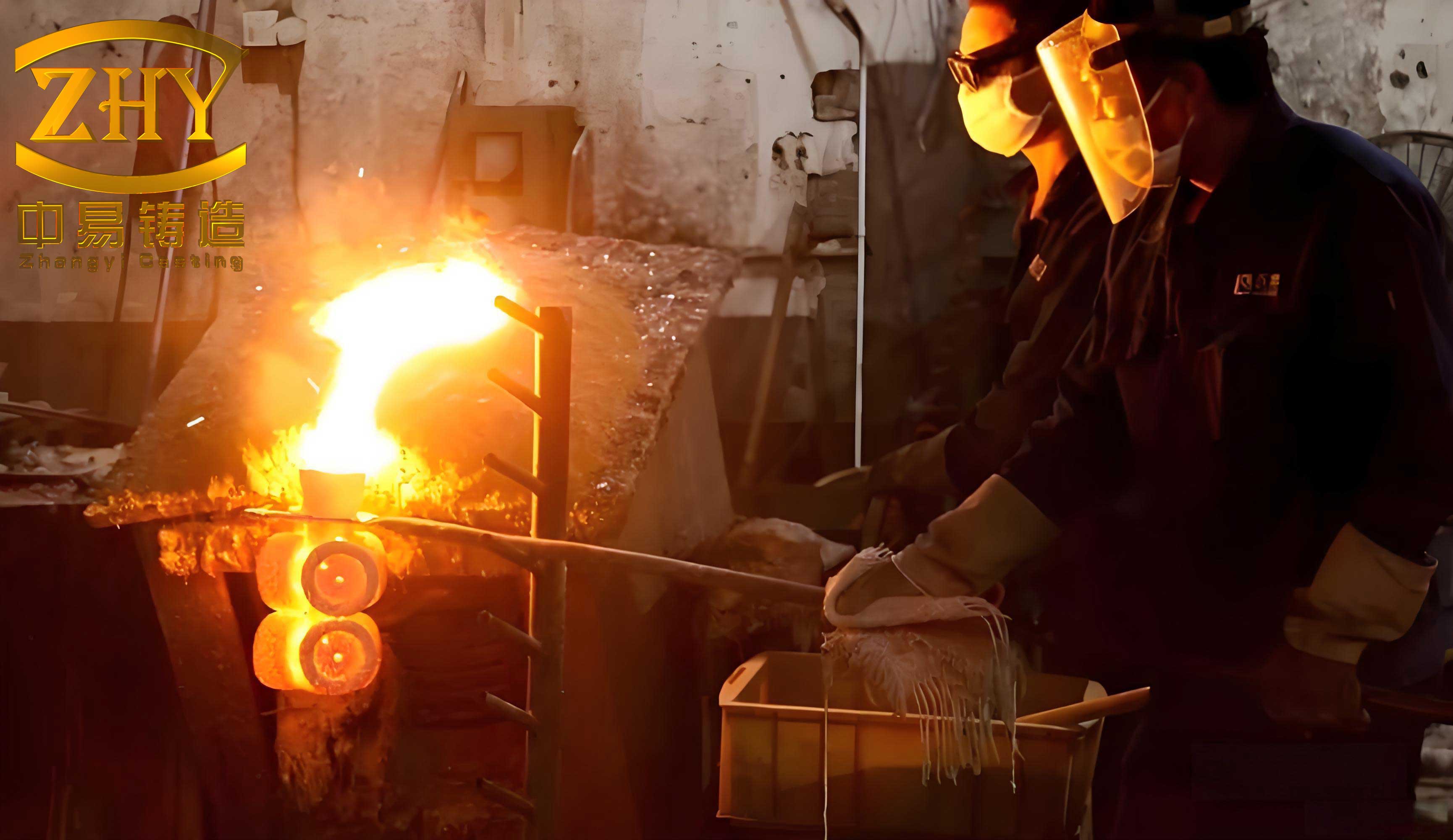
The A356 melt was refined with 0.5 wt% hexachloroethane added in five increments to the depth of the melt. Refining lasted about 20 min at 750 °C, followed by a 15 min holding period. The shell was checked for gate and riser integrity and poured by gravity at 750 °C with a shell temperature of 500 °C and a pouring velocity of 80 mm/s. The pour was kept continuous so that the pouring cup remained full, minimizing air entrainment. After 1–2 h of natural cooling, the castings were cleaned, sandblasted, cut, and given a T6 heat treatment to refine the microstructure and relieve residual stress.
The cast impeller showed no obvious shrinkage porosity or cracking after cleaning and heat treatment. Dimensional accuracy was in the CT4–CT5 range, and the surface roughness was about Ra 3.2 µm, meeting the stated service requirements. The result supports the combination of side-step gating and the optimized pouring parameters for this geometry.
Process Implications
The case shows that a top-pouring system can fill a thin-walled impeller without visible misrun and still produce a serious feeding defect. The critical issue is not whether the cavity fills, but whether the thermal path allows the last-solidifying regions to remain connected to a liquid reservoir. In this impeller, the 3 mm blade sections acted as a thermal barrier: once they solidified, the lower ring could no longer be fed through the central path. The side-step gating system changed the problem by introducing multiple feeding paths around both annular faces, increasing static pressure, and delaying isolation of the lower ring.
The orthogonal study also identifies a practical control point. Pouring velocity had the largest reported effect on the combined response, yet the validation casting was poured manually. Manual pouring can introduce run-to-run variation in velocity, stream continuity, and gate impingement. For production, the optimized window of 750 °C pouring temperature, 80 mm/s pouring velocity, and 500 °C shell preheat should therefore be supported by controlled pouring equipment and routine verification of shell preheat and melt temperature. The simulation results are comparative rather than absolute: interface heat-transfer coefficients, shell permeability, and alloy nucleation conditions can shift the predicted shrinkage level, so the thermal criteria are most reliable when calibrated against castings from the same foundry practice.
Conclusions
- The initial top-pouring design filled the impeller cavity in about 8 s without misrun, but the thin blades solidified early and isolated the lower ring. The predicted shrinkage formed a ring-shaped zone at the bottom of the casting, with 0.67–1.33% porosity, and could not be removed by pouring-parameter changes alone.
- A vertical side-pouring system with a reverse sprue, multiple ingates on both annular faces, top connections, and 7°/3° ingate inclination improved static pressure and feeding. The casting solidified at about 835 s, while the gating system remained liquid until about 1870 s; shrinkage was largely transferred to the gating system.
- The L9 orthogonal simulation selected 750 °C pouring temperature, 80 mm/s pouring velocity, and 500 °C shell preheat as the best combination. This condition gave the lowest maximum effective stress, 113.2 MPa, and the lowest shrinkage porosity, 0.646%, among the nine trials.
- A full investment casting trial using WM36-4 wax, a four-layer silica-sol/quartz-glass/bauxite shell, controlled melting, and gravity pouring produced an impeller with no obvious shrinkage defects. The casting met CT4–CT5 dimensional accuracy and Ra 3.2 µm surface roughness.
- The dominant influence of pouring velocity makes process control a key production requirement. Simulation is effective for comparing gating designs and narrowing parameter windows, but the predicted defect levels should be validated against foundry-specific thermal and filling conditions.