
Exhaust elbows on high-horsepower diesel engines are not simple ducts. They carry hot, oxidizing exhaust gas, experience repeated thermal cycling, and must remain gas-tight while fitting into a compact exhaust route. A common manufacturing route divides the elbow into a cast bend, a machined straight tube, and machined flanges, then joins the parts by welding. That approach avoids the hardest one-piece molding problem, but it introduces weld heat-affected zones, distortion of thin walls, weld inspection, machining stock, and multiple fixtures. For a thin-wall elbow, the welded junction is also a geometric discontinuity where thermal fatigue and oxidation can concentrate.
Integral investment casting changes the manufacturing logic. The elbow can be produced as a single thin-wall shell, with machining limited to the flange faces and bolt holes. The difficult part is not the casting process itself but the feeding strategy: the flange is thick, the straight section and bend are thin, and the alloy has a wide freezing range. A gating system that feeds the thin walls will freeze before it can feed the flange; a system that feeds the flange too aggressively can create turbulence, shell erosion, and hot spots in the bend. The practical task is therefore to place feed metal at the thermal center, keep the thin walls outside the feed path, and verify the filling and solidification sequence before cutting metal.
Geometry, alloy, and defect risk
The elbow envelope is 217 mm × 150 mm × 120 mm. The straight section is 93 mm long, with an outside diameter of 90 mm, an inside diameter of 87 mm, and an average wall thickness of about 1.5 mm. The bend is approximately 90° and ends in a 20° outward flare; its average wall is also below 2 mm. The flange is 16 mm thick, has a 91 mm bore, and contains two annular grooves 13 mm deep and less than 6 mm wide. The wall between the two grooves is no more than 2.5 mm. These proportions define the casting problem: the flange is the only substantial thermal mass, while the rest of the part is a thin shell that loses heat rapidly.
Only the two flange faces and the four Ø11 mm holes are machined. A 3 mm allowance is left on the flange faces; the remaining geometry is cast to size. Acceptance requires complete filling, no visible shrinkage cavity or penetrating defect, no surface cracks, and internal shrinkage no larger than 2 mm, no more than three isolated shrinkage indications, and spacing greater than the sum of the mixed shrinkage diameters. Gas pores and cracks are not permitted.
The alloy is 1Cr20Ni14Si2, a high-chromium nickel austenitic heat-resistant stainless steel specified under GB/T 4238-1992 and later designated 16Cr20Ni14Si2. Its measured composition is close to the standard range, with about 21.66% Cr, 12.44% Ni, 1.70% Si, and 0.0629% C. Chromium forms a dense Cr2O3 surface film; nickel stabilizes austenite; silicon improves high-temperature oxidation resistance. The alloy is nevertheless sensitive to sulfur-bearing environments and has an embrittlement tendency at 600–800 °C, so the exhaust environment is not benign.
| Condition | C | Cr | Ni | Si | Mn | P | S | Fe |
|---|---|---|---|---|---|---|---|---|
| Standard range | ≤0.20 | 19–22 | 12–15 | 1.5–2.5 | ≤1.5 | ≤0.035 | ≤0.03 | Balance |
| Measured heat | 0.0629 | 21.66 | 12.44 | 1.70 | 1.02 | 0.0296 | 0.0055 | Balance |
The specified minimum mechanical properties are also relevant to the process window. The alloy requires at least 590 MPa tensile strength, 295 MPa yield strength, 35% elongation, and 50% reduction of area, with a hardness of 187 HB. Compared with the reference 06Cr25Ni20 alloy used in some imported high-horsepower engines, 1Cr20Ni14Si2 offers higher tensile and yield strength at similar ductility, although its chromium content is lower.
| Alloy | Tensile strength (MPa) | Yield strength (MPa) | Elongation (%) | Reduction of area (%) | Hardness (HB) |
|---|---|---|---|---|---|
| 1Cr20Ni14Si2 | ≥590 | ≥295 | ≥35 | ≥50 | 187 |
| 06Cr25Ni20 | ≥515 | ≥205 | ≥35 | ≥50 | ≤182 |
Thermophysical calculation with the Scheil model in ProCAST gives a liquidus of 1440 °C and a solidus of 1268 °C, a freezing range of 172 °C. Density is about 7.8 g/cm³ at 25 °C and falls rapidly near the liquidus. Between solidus and liquidus the viscosity drops steeply, so feeding is highly sensitive to superheat and shell temperature. The wide freezing range also means that a mushy zone can persist in the flange while the thin walls are already solid, which is exactly the condition that produces shrinkage in the thick section and hot tearing at the thin-to-thick transition.
Gating architecture and simulation setup
Two gating architectures were compared. In the first, two ingates were placed on the largest outer diameter of the flange and fed from below. In the second, four ingates were placed on the flange ears and fed from the side. The flange hot spot was approximated as a 15 mm equivalent hot-spot diameter using the gate-cup capacity feeding method. The two large ingates were sized 55 mm × 22 mm; the four small ingates were 15 mm × 22 mm. The first scheme was arranged as a two-casting tree, while the second was a single-casting tree because the smaller ingates and side-feed arrangement limited shell strength and handling convenience.
| Scheme | Ingate position | Number | Size per ingate (mm) | Filling mode | Castings per tree |
|---|---|---|---|---|---|
| 1 | Largest outer diameter of flange | 2 | 55 × 22 | Bottom fill | 2 |
| 2 | Four flange ears | 4 | 15 × 22 | Side fill | 1 |
Simulation was performed with ProCAST 2018 using a finite-element mesh. The casting surface mesh was set to 1 mm and the gating system to 3 mm; the shell was generated at 9 mm. Gravity was set along −Y. The interface heat-transfer coefficient between metal and shell was fixed at 900 W/(m²·K), selected from a range of 300–900 W/(m²·K). The initial pouring parameters were 1550 °C, 3 kg/s, and an 800 °C shell preheat. The alloy was treated as elastic–plastic for stress calculation, and the shell was allowed to cool in air at 10–20 °C.
Microshrinkage was screened with the Niyama criterion:
$$M=\frac{G}{\sqrt{R}}$$
where G is the local temperature gradient and R is the cooling rate through the freezing interval. A lower M indicates a higher susceptibility to interdendritic shrinkage; the critical value depends on alloy composition. Hot tearing was screened with the hot-tearing indicator (HTI) and effective stress. A higher HTI indicates a greater tendency toward hot cracking, while the effective stress was compared with the alloy’s specified minimum yield strength as a relative engineering threshold, not as a high-temperature fracture criterion.
Gating selection: feed the flange, not the thin wall
Both schemes filled completely without misrun or cold shut. In scheme 1, the two-casting tree filled in 9.81 s and completed solidification in 1743 s. Some turbulence occurred in the sprue during the early stage, but it did not enter the casting cavity; the bottom-filled ingates delivered metal into the thick flange and allowed the thin walls to solidify first. In scheme 2, the single-casting tree filled in 2.78 s and solidified in 2432 s. The trees had different masses, so fill and solidification times are not normalized; the useful comparison is the defect pattern and the thermal sequence.
Scheme 1 produced 1.06 cm³ of shrinkage per casting, compared with 1.26 cm³ in scheme 2. In scheme 1, the shrinkage was concentrated in the flange ears; the thin straight section and bend were essentially free of shrinkage. In scheme 2, shrinkage was distributed over the thin straight section and bend as well as the flange, which is consistent with the smaller side ingates freezing before they could feed the thick section. The hot-tearing indicators showed the same ranking. At the bend crown, scheme 1 gave an HTI of 0.000163 and an effective stress of 439.5 MPa; scheme 2 gave 0.000204 and 569 MPa. At the maximum-HTI location, scheme 1 gave 0.000760 and 258 MPa; scheme 2 gave 0.000777 and 279.7 MPa. The bend-crown stress exceeded the room-temperature yield strength in both designs, but its HTI remained low; the maximum-HTI location stayed below 295 MPa in both cases.
| Scheme | Shrinkage per casting (cm³) | A stress (MPa) | A HTI | B stress (MPa) | B HTI | Trial observation |
|---|---|---|---|---|---|---|
| 1 | 1.06 | 439.5 | 0.000163 | 258 | 0.000760 | Minor surface defects; sectioned flange sound |
| 2 | 1.26 | 569 | 0.000204 | 279.7 | 0.000777 | Visible shrinkage on surface |
Trial castings at the initial parameters confirmed the ranking. Scheme 1 showed only minor surface defects, and the sectioned flange was sound. Scheme 2 showed clearly visible shrinkage on the casting surface and did not meet the visual requirement. Scheme 1 was therefore selected for parameter optimization. The result is consistent with the feeding principle: the thick flange must be fed through large ingates, and the thin walls should not be used as feed paths.
Process window: superheat, fill rate, and shell temperature
With the gating fixed, one variable at a time was varied in simulation. Pouring temperature was tested from 1530 to 1650 °C in 20 °C steps; pouring rate from 1.5 to 4.5 kg/s in 0.5 kg/s steps; shell preheat from 750 to 1050 °C in 50 °C steps. The initial condition remained 1550 °C, 3 kg/s, and 800 °C.
| Variable | Range | Best value | Reported shrinkage result | Trend |
|---|---|---|---|---|
| Pouring temperature | 1530–1650 °C | 1650 °C | 1.45 cm³ for the two-casting tree, about 31% below the 2.12 cm³ result at 1550 °C | Higher superheat reduced thin-wall shrinkage; residual shrinkage remained in the flange ears |
| Pouring rate | 1.5–4.5 kg/s | 1.5 kg/s | 1.77 cm³ for the tree | Lowest rate gave the least shrinkage; above 3.5 kg/s shrinkage rose sharply |
| Shell preheat | 750–1050 °C | 1050 °C | 0.81 cm³ for the two-casting tree, about 62% below the 2.12 cm³ result at 800 °C | Higher shell temperature reduced shrinkage; thin-wall shrinkage fell to zero |
At 1650 °C, the two-casting shrinkage total fell to 1.45 cm³ and the thin-wall shrinkage disappeared; the remaining indications were confined to the flange ears, which are later machined for the Ø11 mm holes. At 1.5 kg/s, the total was 1.77 cm³; increasing the rate to 4.5 kg/s raised it to 3.91 cm³. A slower pour reduces jetting and shell impingement, but it must still fill the 18 kg tree before cold shut; the optimized trial filled in 12 s, which corresponds to 1.5 kg/s. At a shell preheat of 1050 °C, the two-casting total fell to 0.81 cm³ and the thin-wall shrinkage again disappeared.
The mechanism is coupled. Higher superheat and higher shell temperature keep the mushy zone alive longer and preserve a feed path from the ingate to the flange. A slower fill reduces impact pressure and shell erosion, which lowers the risk of sand inclusion and turbulence-related defects. These gains are bounded: excessive superheat promotes oxidation, gas pickup, and coarse grains, and plant practice places an upper limit near 1660 °C for silica-sol shells. The selected 1650 °C gives about 210 °C superheat, just below that ceiling. A very high shell temperature can also coarsen the microstructure and soften the shell, so 1050 °C is a process compromise rather than a universal optimum.
Combined optimum and hot-tearing screen
Combining the three single-factor optima gave 1650 °C, 1.5 kg/s, and 1050 °C. The two-casting shrinkage total fell from 2.12 to 0.75 cm³, about a 65% reduction. The better casting contained 0.073 cm³, about 93% below the initial per-casting value of 1.06 cm³. Shrinkage in the thin straight section and bend was eliminated; the remaining indications were in the flange ears and were removed during machining.
| Parameter set | Pouring temperature (°C) | Pouring rate (kg/s) | Shell preheat (°C) | Shrinkage in one casting (cm³) |
|---|---|---|---|---|
| Initial | 1550 | 3.0 | 800 | 1.06 |
| Temperature only | 1650 | 3.0 | 800 | 0.64 |
| Rate only | 1550 | 1.5 | 800 | 0.87 |
| Shell only | 1550 | 3.0 | 1050 | 0.405 |
| Combined | 1650 | 1.5 | 1050 | 0.073 for the best casting; 0.75 for the two-casting tree |
Hot tearing at the combined optimum was also lower. The HTI at the bend crown was 0.000437, and the maximum-HTI location was 0.000440, compared with 0.000760 at the maximum-HTI location under the initial parameters. At the end of solidification the computed effective stress in both regions was below 100 MPa. During later cooling the model showed stress rising to 484 MPa at the bend crown and 261 MPa at the maximum-HTI location, so residual stress remains a separate design consideration even though no hot cracks were found. The comparison with 295 MPa is only a relative screen because that value is a room-temperature specification; the high-temperature strength of the alloy is lower, and the HTI is not a fracture criterion.
Foundry validation and CT inspection
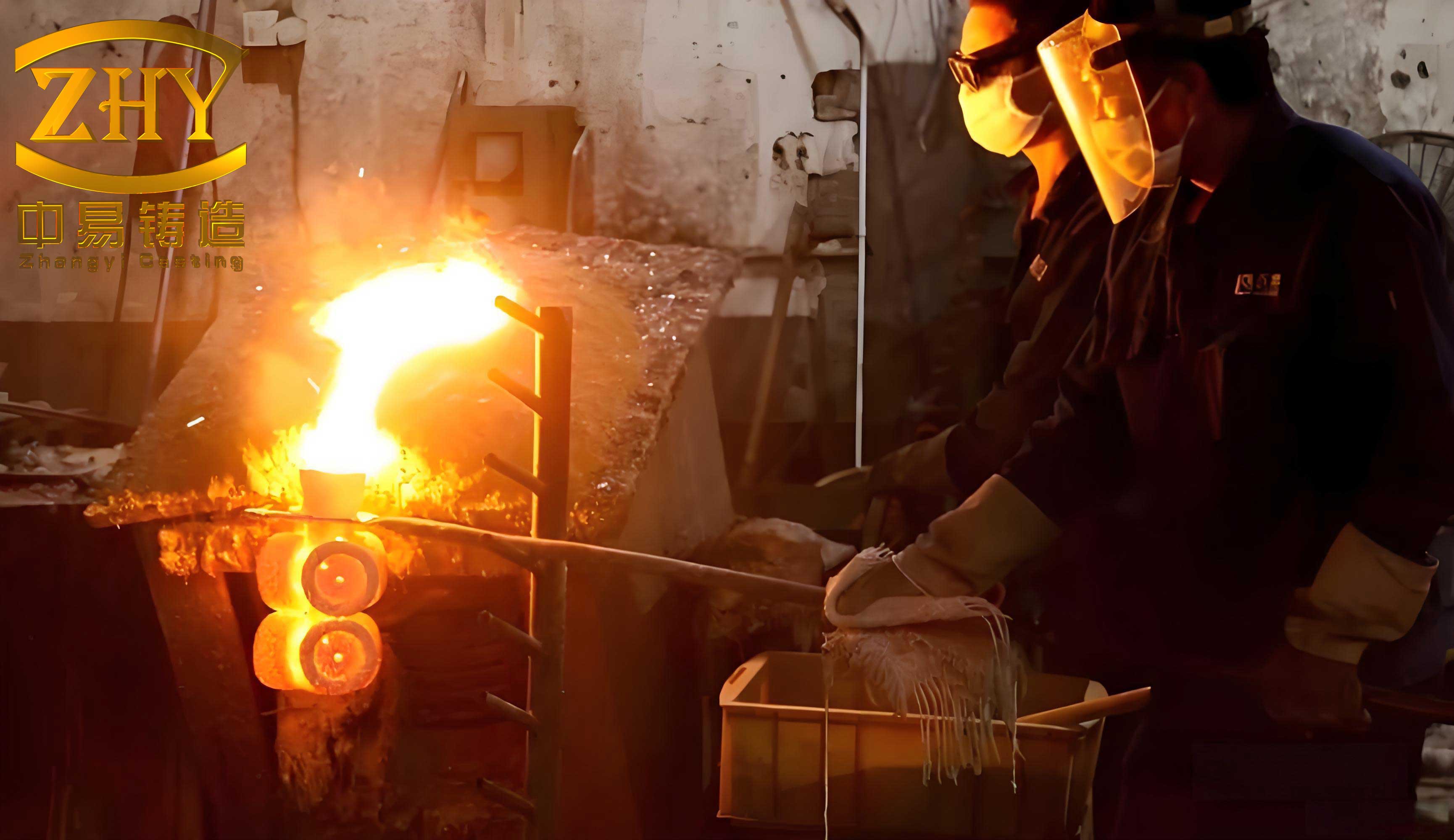
The production route used a fully refined paraffin wax with a shrinkage below 1%, tensile strength above 1.4 MPa, and bending strength of 5–8 MPa. Wax was injected at 57–58 °C with a 60 s hold. Because the 90° bend and the sub-6 mm ring grooves make one-piece pattern removal difficult, a fixed extraction sequence was used and the pattern was cooled in water before trimming. The shell used a silica-sol binder, a zircon face coat, and mullite backup layers. Four and a half layers produced a 9–10 mm shell. The face layer was dried for 15 h and the backup layers for 24 h; the longer drying time was needed to prevent incomplete drying inside the narrow ring grooves, which otherwise caused metal penetration and sand inclusion. Dewaxing was carried out at 0.7–0.8 MPa and 160 ± 10 °C for 15–20 min, followed by calcination at 1150–1180 °C for 30–60 min and a 30 min hold.
Before pouring, the shell was preheated to 1050 °C; the furnace was set 40–50 °C above the target to compensate for transfer loss. The 18 kg tree was filled in 12 s at 1.5 kg/s, consistent with the optimized rate. After cooling, the castings were knocked out, cut from the ingates, ground, shot blasted, pickled, and passivated in 10% HF + 20% HNO3 at 45–50 °C for 2–5 min, neutralized with 7–10% NaOH, and rinsed in 80–100 °C water. Low-impact knockout was used to avoid distorting the thin walls.
Dimensions were checked with calipers and a coordinate measuring machine. The wall thickness and the 70 ± 0.5 mm center distance were within tolerance. Internal quality was checked by industrial CT (ICT-450) under GB/T 29070-2012, using 430 kV, 1.5 mA, a 0.4 mm focal spot, 1000 ms integration, a source–detector distance of 1100 mm, a source–object distance of 700 mm, 1600 projections, and a 0.127 mm voxel size in standard cone-beam mode. The acceptance criteria were shrinkage no larger than 2 mm, no more than three indications, adequate spacing, and no gas pores or cracks.
At the initial parameters, CT found a shrinkage cavity in the bend and dense gas pores in the straight section; no cracks were found. The simulated bend shrinkage volume at those parameters was 0.0177 cm³, and the CT cavity was located at the same position, which supports the filling and feeding model. At the combined optimum, CT sections through the bend, straight section, and flange showed no shrinkage, no gas pores, and no cracks. Visual inspection also improved: the initial castings showed oxide scale, mottling, and wrinkled skin, and some required dressing or welding; the optimized castings had clean surfaces and passed dimensional inspection. Across the 12-piece trial, 10 castings were acceptable, a yield of 83.3%.
What the results mean—and where the model stops
The central design rule is to feed the thick flange and let the thin walls solidify first. Large bottom ingates on the flange outer diameter provide a short, wide feed path and keep the fill velocity in the cavity moderate. Small side ingates on the flange ears look convenient for pattern assembly, but they freeze early, starve the flange, and distribute shrinkage into the bend and straight section. The trial castings and CT results support that interpretation: the gating change reduced shrinkage before any parameter optimization, and the parameter change then removed most of the remaining thin-wall shrinkage.
The combined window of 1650 °C, 1.5 kg/s, and 1050 °C works because it slows cooling in the flange, preserves feeding, and avoids the turbulence produced by a fast pour. It is not a universal recipe. The high shell temperature can coarsen the microstructure, the high superheat increases oxidation and gas pickup, and the slow fill leaves little margin against cold shut in thinner sections. The window is therefore bounded by both defect modes: shrinkage on the slow-cooling side and misrun or oxidation on the fast-heating side.
The model also has limits. The interface heat-transfer coefficient was fixed at 900 W/(m²·K), whereas the real value varies with shell thickness, shell temperature, and contact condition. The Niyama criterion is suited to interdendritic microshrinkage and does not predict all macroscopic shrinkage cavities. The HTI and effective stress are relative indicators, and the 295 MPa yield strength is a room-temperature specification, not a high-temperature fracture criterion. Residual stress after cooling was calculated but not experimentally mapped, and the production trial covered 12 castings of one geometry. Within those limits, integral investment casting with the flange-fed gating system and the 1650 °C/1.5 kg/s/1050 °C window produced thin-wall exhaust elbows that met dimensional, visual, and CT acceptance requirements without the welds and multiple machining setups of the assembled route.