
Large shell-type castings are used in machine tool beds, wind turbine gearbox housings, compressor casings, and other heavy equipment. Their dimensions are large, their wall thickness varies sharply, and their internal cavities, flanges, ribs, and locating features are often integrated into one body. These features make dimensional control difficult: the pattern must hold its shape through coating and sand compaction, the mold must support a thin shell under vacuum, and the solidifying metal must contract without distorting the overall frame. A compressor-housing case with a 1,200 mm × 820 mm × 800 mm envelope and 18–60 mm walls illustrates the problem. The same part contains thin walls, thick flanges, and large planar faces, so pattern deflection, coating shrinkage, sand movement, and solidification contraction can all push critical features away from nominal dimensions.
Accuracy Requirements and Process Context
Large shell castings commonly range from about 1,000 mm to 4,000 mm in length, with wall thickness from roughly 10 mm in thin regions to 80 mm in heavy sections. Functional tolerances are tight relative to these section changes: flange flatness is often required to be within 0.3 mm/m, hole spacing within ±0.5 mm, and shaft-hole coaxiality within 0.1 mm. These requirements are coupled. A flatness error on a flange can change hole alignment and assembly stress, while a local pattern distortion can propagate into a global height or spacing error.
Lost foam casting removes several traditional constraints. A polymeric pattern, identical in shape to the casting, is assembled into a cluster, coated with refractory, dried, buried in dry quartz sand, and compacted by vibration under vacuum. Molten metal then fills the cavity as the pattern gasifies. Because there is no parting line, no draft angle, and no sand core, the process is well suited to complex, integrated shells. The pattern, however, is a temporary tool that is consumed during filling. Dimensional control therefore shifts from mold parting and core assembly to pattern stability, coating stiffness, sand support, gas removal, and solidification uniformity.
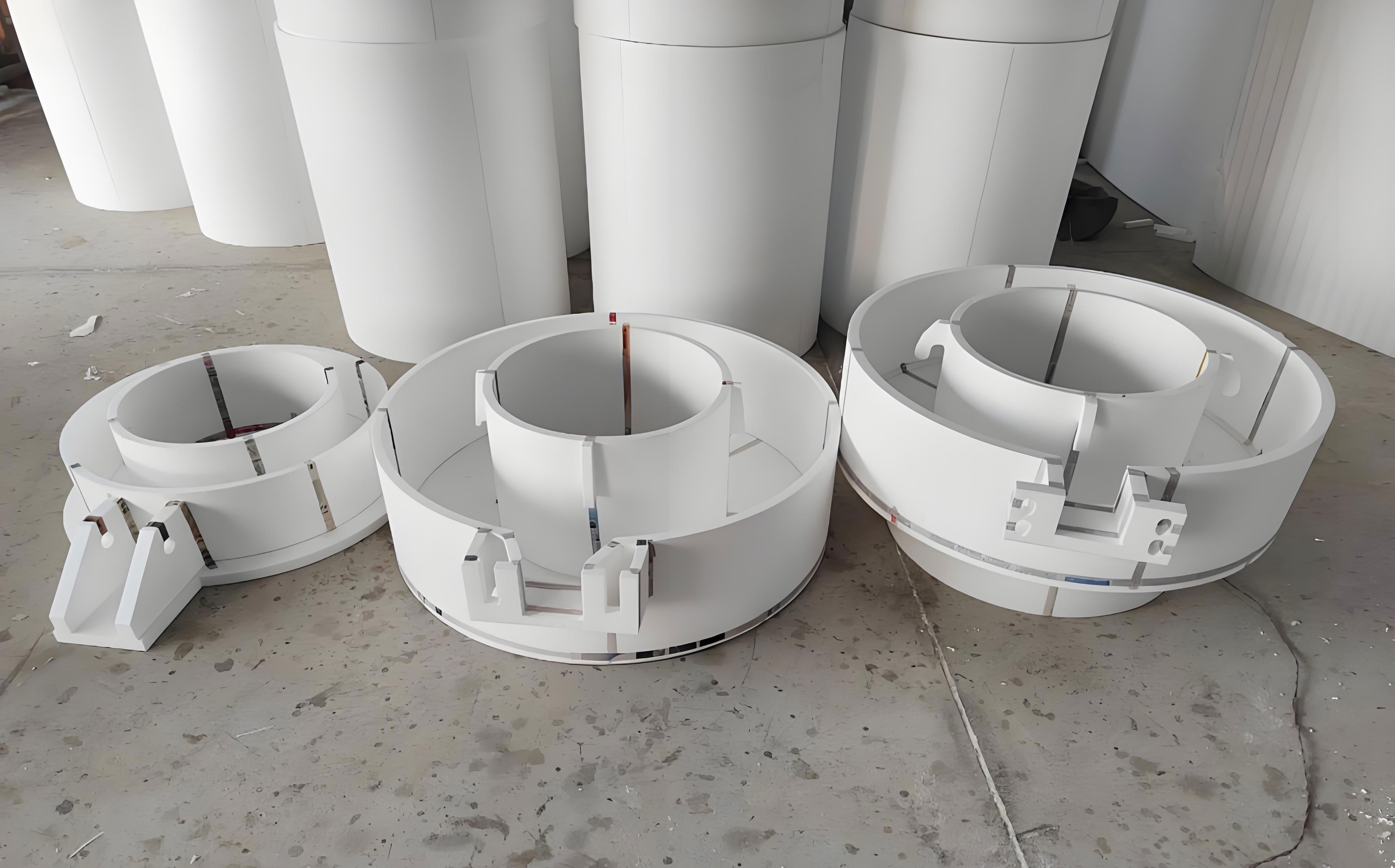
Dimensional control begins with pattern compensation but does not end there. The coating adds stiffness and controls surface quality; the sand bed supports the cavity; vacuum removes pyrolysis products; pouring temperature and fill rate determine whether gas escape and solidification proceed uniformly. Each stage can correct or amplify an error produced earlier in the chain.
Where Dimensional Error Accumulates
Pattern shrinkage and thermal distortion. Expandable polystyrene and modified foams used for patterns typically have densities of 18–30 kg/m³. Pattern making itself introduces linear dimensional error of about 0.3–0.5%. High temperature or fluctuating humidity can release internal stress, cause local collapse, or change the pattern profile. During pouring, the pattern gasifies; nonuniform gasification changes the cavity contour and can produce local mismatch. If compensation, venting, and support are poorly arranged, local dimensional mismatch can reach 2–3 mm. Thin walls and large flat panels are especially vulnerable because they have low bending stiffness and are sensitive to material softening and rebound. Errors also accumulate over the full length, so a small local distortion can become a global flatness or hole-position problem.
Coating drying and mold deformation. Refractory coatings shrink about 0.1–0.3% linearly on drying. Uneven drying or poor ventilation can warp or crack the coating at corners and internal cavities. In multilayer coatings, different drying rates between layers create surface-tension gradients, causing shelling or local bulging that changes the pattern profile. The sand mold is not rigid: its stiffness depends on compaction density and vacuum uniformity. Weak sand-box support or uneven vacuum can displace sand and rotate the pattern slightly. In large shells, such movement can produce planar offsets reported at up to 12 mm in severe cases, directly affecting flange flatness and symmetry.
Solidification contraction. Gray iron contracts about 0.8–1.0% linearly during solidification; ductile iron can reach 1.3%. Thin sections cool quickly, generating contraction stress that may curl edges or produce depressions. Thick sections cool slowly and can develop shrinkage porosity and surface sinks. If the gating system feeds different regions unevenly, one side of the housing may contract more than the other, producing tilt or twist rather than a simple size error.
Process fluctuations. Vacuum in the range −0.03 to −0.06 MPa gives stable cavity support. Fluctuations beyond about ±0.01 MPa change the support force and can leave incomplete pyrolysis products. A 10 °C rise in pouring temperature can advance pattern gasification by roughly 0.1 s, enlarging fillet radii and pushing external dimensions outward. A temperature below the window reduces fluidity and leaves corners unfilled. Vibration is normally held at 40–60 Hz; insufficient compaction creates nonuniform sand stress and promotes depression or distortion along long edges.
Pattern Stiffness and Differential Compensation
For shells longer than 2,000 mm, a metal skeleton or internal ribs can be embedded in the foam pattern to limit sag and thermal distortion. The bending stiffness of the pattern can be approximated as
$$K = \frac{3EI}{L^3}$$
where \(E\) is the elastic modulus of the foam, \(I\) is the second moment of area of the pattern section, and \(L\) is the free span. High-density rigid polyurethane foam has \(E\) of about 15–30 MPa; high-density polystyrene foam is lower, about 2–5 MPa. Because stiffness falls with the cube of span, supporting a long pattern at intervals is more effective than increasing wall thickness locally.
Shrinkage compensation should be differentiated by region. A common linear allowance is 1.0–1.2%, with an additional 0.2–0.3% overcompensation at ribs, thin reinforced zones, and features that experience local restraint. A single uniform scaling factor is inadequate for a shell with 10 mm walls and 80 mm flanges: thin sections and massive sections do not shrink at the same rate or respond to the same thermal history.
Coating and Drying Control
The coating formulation and application sequence affect both the stiffness of the coated pattern and its gas permeability. A Baume degree of about 70 °Bé corresponds to 55–60% solids, giving a viscosity that coats uniformly without sedimentation or running. Filler particle size should be 20–50 μm, which helps form a dense layer with useful permeability. Dry coating thickness is typically 0.5–1.2 mm, built up in 3–5 layers.
Drying should be staged. Natural drying at 25–30 °C for 48 h is acceptable; infrared or hot-air drying can shorten the cycle but should not exceed 60 °C. Linear drying shrinkage should remain below 0.2%, estimated from
$$\varepsilon = \frac{L_0 – L_d}{L_0}\times 100\%$$
where \(L_0\) is the initial length and \(L_d\) is the length after drying. Excessive shrinkage deforms the cavity and compromises dimensional stability. The coating also has a permeability limit: increasing layer count raises stiffness and can reduce hole-distance error, but a coating that is too thick or too dense impedes vapor escape and can cause gas defects. The 3–5 layer range is therefore a compromise between shell stiffness and venting. Because dried coatings absorb moisture, pouring should follow drying within 48 h.
Pouring Temperature, Vacuum, and Filling Stability
For cast iron, a pouring temperature of 1,370–1,420 °C is about 150–200 °C above the 1,140–1,200 °C liquidus range. This window provides enough superheat for filling and gas removal without excessive pattern gasification. Aluminum alloys are poured at 700–730 °C, about 70–120 °C above their 580–630 °C liquidus range. A pouring rate of 1.5–2.5 kg/s is typical, adjusted for section volume and pattern stability.
Vacuum should be held at −0.04 to −0.06 MPa during filling, within a broader stable range of −0.03 to −0.06 MPa. The vacuum assists vapor removal and supports the sand cavity, but it must be steady; fluctuations change the support state and can produce dimensional drift. For shells with large spans, dual-channel synchronized pouring or an insulating shell can reduce asymmetric cooling and contraction. Temperature and vacuum should be treated as a coupled pair: higher temperature lowers viscosity but accelerates gasification, while stronger vacuum removes gas but changes the mechanical support of the mold.
Simulation and Feedback Correction
Finite-element simulation can couple the thermal, flow, and stress fields, with modules for pattern ablation, metal filling, and solidification shrinkage. Inputs include the gasification-rate curve of the foam, the coating thermal conductivity, typically 0.2–0.6 W/m·K, and the thermophysical properties of the metal. Simulation is most useful as a correction tool: it identifies likely offsets before tooling is cut, and the predicted offsets are fed back into pattern compensation and process setpoints.
A compact empirical form used to organize the correction is
$$\Delta L = f(T, V, \varepsilon_s, P)$$
where \(\Delta L\) is dimensional deviation, \(T\) is metal temperature, \(V\) is filling velocity, \(\varepsilon_s\) is pattern shrinkage ratio, and \(P\) is vacuum level. The function is not a substitute for measured castings; it provides a structured way to adjust the process when one variable changes. Measured dimensions remain the calibration source for the next pattern iteration.
Experimental Validation on a Compressor Housing
The case component was a large compressor housing with an envelope of approximately 1,200 mm × 820 mm × 800 mm, wall thickness from 18 to 60 mm, and a mass of about 1 t. The pattern was molded from expandable polystyrene at a density of 22 kg/m³. After multilayer coating, the pattern was steam-dried for at least 48 h at about 50 °C, buried in quartz sand, and compacted under vacuum vibration at 40, 45, and 40 Hz. Pouring was stepped, with thermocouple control holding the temperature within ±5 °C; in-mold cooling exceeded 8 h before shakeout.
Dimensional inspection used a 3D laser scanning system, with critical features rechecked by a coordinate measuring machine with a measuring accuracy of ±0.02 mm. Twelve positions were monitored, including shell diagonals, the four corners of the flange plane, the height centerline, and locating-hole centers. Three samples were measured per group and averaged; each parameter group was repeated at least three times.
| Parameter set | Pouring temperature (°C) | Vacuum (MPa) | Coating layers | Flange flatness error (mm) | Shell height deviation (mm) | Hole-distance error (mm) |
|---|---|---|---|---|---|---|
| 1 | 1,380 | −0.03 | 3 | 0.92 | +2.44 | −1.35 |
| 2 | 1,400 | −0.045 | 4 | 0.58 | +1.67 | −0.84 |
| 3 | 1,420 | −0.06 | 5 | 0.36 | +0.89 | −0.42 |
Positive height deviation indicates an oversized shell; negative hole-distance error indicates undersized spacing. The three rows represent combined changes in temperature, vacuum, and coating thickness, not a single-factor factorial design. The trend therefore supports the coupled process window rather than isolating the effect of any one variable. With the progression from set 1 to set 3, flange flatness error fell from 0.92 to 0.36 mm, shell height deviation from +2.44 to +0.89 mm, and hole-distance error from −1.35 to −0.42 mm. At the final setting, all three monitored errors are within ±1 mm.
The direction of the changes is consistent with the process mechanisms. Higher pouring temperature improves filling and reduces incomplete gasification that can cause local dimensional overflow; stronger vacuum improves pattern support and removal of pyrolysis products; additional coating layers raise cavity stiffness and reduce hole-distance error. The same result also shows the limit of the coating strategy: layer count cannot be increased indefinitely without risking trapped gas and related defects.
Engineering Implications and Limits
The case supports a coupled control strategy for large shell castings: pattern stiffness and differential compensation, coating thickness and drying, pouring temperature and vacuum, and simulation-based correction should be managed as one system. The final dimensional window of ±1 mm was achieved on a 1 t compressor housing with 18–60 mm walls, using the parameter set in Table 1. That result is relevant to similar large, thin-walled, integrated shells where pattern deformation and solidification gradients are the dominant error sources.
The evidence also has boundaries. The comparison above changes several parameters at once, and the measurement set covers one housing geometry with three samples per group. It does not establish a general single-variable optimum for all shell castings, nor does it replace a full factorial or design-of-experiments study. For a new geometry, the same framework can be used, but the compensation values, coating schedule, and vacuum window must be recalibrated against measured castings. The practical value of the method lies in controlling the interaction of pattern, mold, and solidification rather than optimizing any one factor in isolation.