
The production of complex, thin-walled components presents a persistent and significant challenge within the foundry industry, demanding a meticulous balance between metallurgical quality, dimensional accuracy, and production yield. This is particularly true for critical parts like compressor valves, where performance is non-negotiable. This article details a comprehensive investigation and subsequent optimization of the casting process for a specific thin-walled valve body manufactured from high-grade spheroidal graphite cast iron. The component, characterized by intricate internal passages and a nominal wall thickness of merely 4 mm, initially suffered from a high scrap rate due to defects such as cold shuts, gas porosity, and core fracture. Through systematic analysis and iterative design modifications focused on gating, feeding, core design, and process parameters, a robust and stable production process was successfully developed.
The valve body under consideration is a quintessential example of a demanding thin-walled casting. Its complex geometry, featuring several long, narrow internal ports, directly contradicts the favorable conditions for sound casting. The primary material is a ductile iron grade equivalent to A-395 (QT400-18L), requiring a minimum tensile strength of 400 MPa and a specified hardness range. The extreme thinness of the sections, combined with the relatively large planar dimensions, creates inherent difficulties in achieving complete mold filling while simultaneously managing solidification shrinkage and core integrity. The internal cavity geometry necessitates the use of a large, complex sand core, which itself becomes a source of potential defects due to its mass, gas evolution, and mechanical stability during metal pouring.
The initial casting process, developed based on conventional wisdom, employed a horizontally-parted mold with a single cavity per pattern. The core was designed as a monolithic structure with connected framework headers to support the slender port features. The gating system was of a semi-choked design, aiming for tranquil mold filling. A single top riser was intended to compensate for shrinkage. Early production trials immediately revealed critical shortcomings. The scrap rate soared above 30%, with defects manifesting in predictable locations: cold shuts on the upper casting surfaces distant from the ingates, gas porosity in isolated blind sections, and fracture of the thin core sections defining the valve ports. A root-cause analysis, supported by initial simulation studies, pinpointed several interconnected issues in the original scheme.
The table below summarizes the primary defects observed and their hypothesized causes from the initial process:
| Observed Defect | Location | Hypothesized Primary Cause |
|---|---|---|
| Cold Shuts | Upper surfaces, far from ingates | Insufficient metal fluidity/velocity; poor venting; low pouring temperature. |
| Gas Porosity (Blowholes) | Isolated blind cavities and upper sections | Inadequate venting of mold and core gases; high gas evolution from massive core. |
| Core Fracture / Metal Penetration | Thin valve port cores (e.g., Ø12mm, Ø15mm) | Insufficient core strength; thermal shock from metal impingement; high pouring temperature. |
| Surface Shrinkage | Transition regions near thicker sections | Ineffective feeding due to riser placement and size. |
The path to a solution required a holistic re-engineering of the process, addressing each flaw systematically. The improvements can be categorized into four major areas: Core Design Optimization, Gating & Pouring System Redesign, Enhanced Venting Strategy, and Metallurgical & Parameter Control.
1. Radical Core Design and Manufacturing Overhaul
The original solid core was a significant liability. Its weight contributed directly to high gas generation, and its monolithic structure did not optimally resist thermal stress. The redesign focused on lightweighting and strengthening. The core was inverted 180 degrees relative to its shooting direction, and the main Ø60mm bore was made hollow with a consistent wall thickness of 12 mm. This dramatically reduced the core’s mass and, consequently, its total gas evolution during casting. The framework headers were maintained for stability but their dimensions were optimized. The new core design reduced weight by approximately 45%, transforming it from a gas-generating mass into a more robust, lightweight structure. The core production process was also refined to ensure complete curing and uniform coating application, guaranteeing maximum hot strength and low gas emission.
2. Gating System Redesign for Rapid, Uniform Filling
The original two-ingate system proved inadequate for such a thin-walled geometry. The fluidity of spheroidal graphite cast iron, while reasonable, is lower than that of gray iron, making fast fill critical to avoid premature freezing. The new system adopted a multi-ingate, bottom-gated approach. The number of ingates per casting was increased from two to five, strategically distributed around the part’s perimeter to ensure simultaneous, rapid filling from multiple points. The ingates were designed as thin, wide chokes to distribute flow without excessive turbulence. This change drastically reduced the flow distance for any metal stream, minimizing temperature loss and the risk of cold shuts. The gating ratio was carefully recalculated to maintain a controlled but swift fill. The pouring temperature was strategically increased by 20°C to a target range of 1400-1450°C, counteracting the rapid heat loss in thin sections. The required pouring time \( t_p \) can be estimated using empirical formulas for thin-wall castings:
$$ t_p = k \cdot \sqrt{W} $$
where \( W \) is the casting weight (kg) and \( k \) is an empirical coefficient dependent on section thickness and complexity. For a 4 mm wall, \( k \) is typically low, demanding a very short \( t_p \), which the multi-ingate system facilitated.
3. Comprehensive Venting Strategy
With the reduced but still significant core gas evolution and the need to evacuate air from the mold cavity quickly, venting became a critical focus. The previous venting was ad-hoc and insufficient. In the optimized process, venting was systematically engineered:
- Core Vents: Multiple vent channels were integrated into the core prints, connected to the external atmosphere through strategically drilled vents in the mold.
- Mold Cavity Vents: Additional vent pins were placed at the highest points of the mold cavity, particularly in areas previously prone to gas accumulation (blind pockets, top of the core framework).
The goal was to provide a low-resistance path for gases to escape ahead of the advancing liquid metal front, described conceptually by Darcy’s law for gas flow through a permeable medium (the sand):
$$ Q = \frac{-k A}{\mu} \frac{dP}{dx} $$
where \( Q \) is the gas flow rate, \( k \) is the permeability of the molding sand, \( A \) is the cross-sectional area of the vent, \( \mu \) is the gas viscosity, and \( dP/dx \) is the pressure gradient. By increasing the vent area \( A \) and ensuring direct paths (minimizing \( dx \)), the pressure \( P \) inside the cavity could be kept low, preventing gas entrapment.
4. Feeding and Solidification Control
Although the casting is predominantly thin-walled, transition regions and junctions act as isolated hot spots prone to shrinkage porosity. The original single riser was inadequate. The feeding strategy was revised to promote directional solidification towards the riser. The riser size and height were increased to ensure it remained molten longer than the casting. The efficacy of a riser can be assessed by its modulus (Volume/Surface Area ratio), which must be greater than the modulus of the region it is intended to feed. The feeding distance \( L_f \) for a thin-walled plate of spheroidal graphite cast iron can be approximated by:
$$ L_f = C \cdot T $$
where \( T \) is the plate thickness and \( C \) is a constant that depends on the effectiveness of the end chill (or riser). By using multiple, strategically placed ingates that also act as thermal feeders early in solidification and a larger top riser, the effective feeding distance was maximized, and internal shrinkage was eliminated.
5. Metallurgical Adjustments
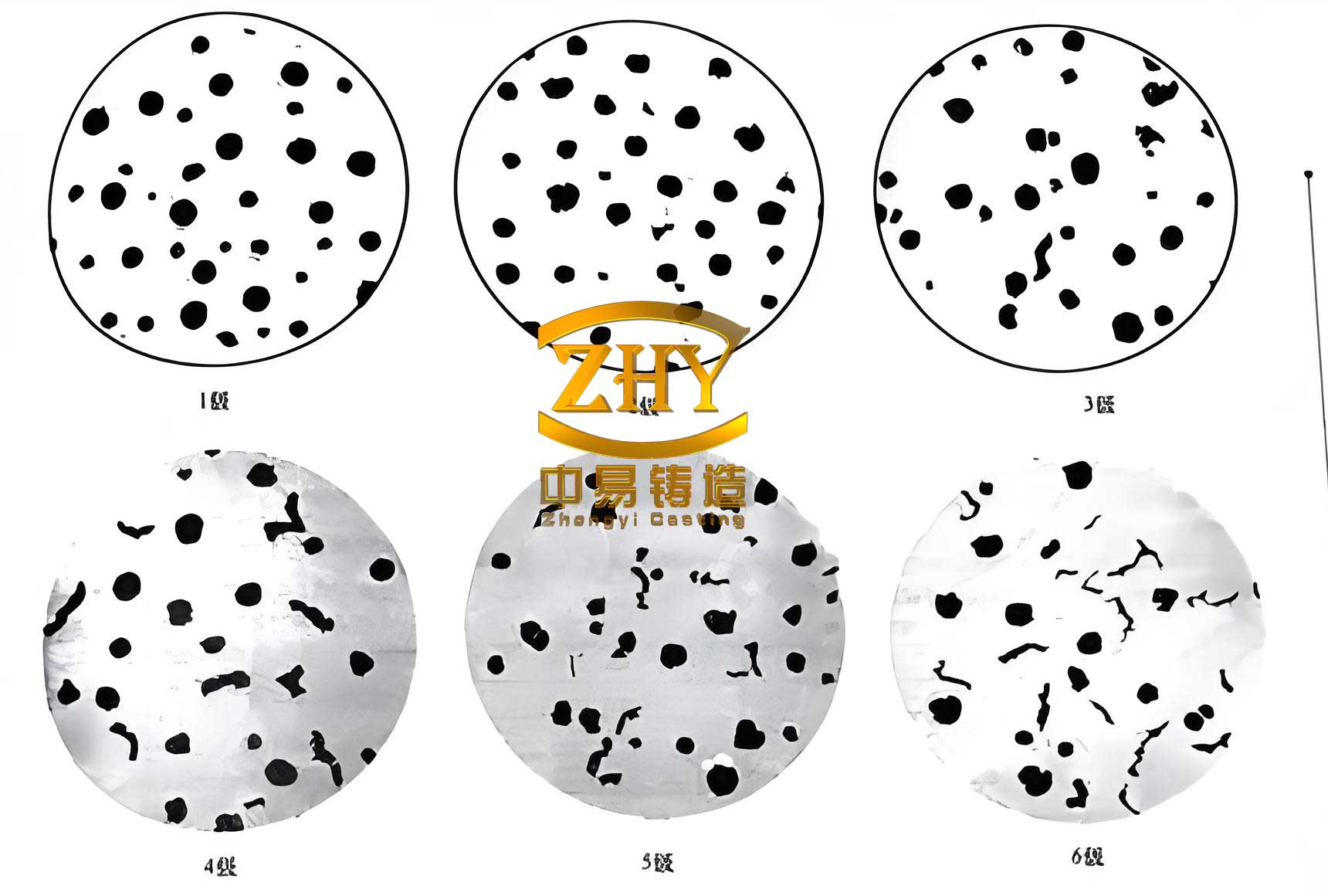
Minor adjustments to the metallurgical practice were implemented to support the improved process. The copper alloying addition was slightly reduced to maintain the desired hardness without adversely affecting the carbon equivalent and graphite morphology. The post-inoculation (stream inoculation) practice was optimized to ensure a high nodule count, which improves the homogeneity and mechanical properties of the thin sections. The target metallurgical parameters for the high-quality spheroidal graphite cast iron are summarized below:
| Parameter | Target Range / Value |
|---|---|
| Carbon Equivalent (CE) | 4.3 – 4.5 |
| Pouring Temperature | 1400 – 1450 °C |
| Post-Inoculation Addition | 1.5 % |
| Nodule Count | > 120 nodules/mm² |
| Nodularity | > 85% |
The culmination of these interconnected optimizations was tested through multiple production trials. The results were transformative. The scrap rate attributed to the targeted defects plummeted from over 30% to below 3%. The castings exhibited excellent surface finish, with sharp contours and complete absence of cold shuts and surface porosity. Dimensional inspection confirmed consistency within the required CT7 tolerance band. Most importantly, the internal soundness of the castings, verified through machining and pressure testing, was confirmed, ensuring the required leak-tight performance of the valve. The process demonstrated robust stability in batch production runs exceeding two thousand pieces.
The successful resolution of these casting challenges underscores several key principles for thin-walled spheroidal graphite cast iron components:
- Integrated System Approach: Gating, venting, core design, and feeding cannot be optimized in isolation; they form a highly interdependent system.
- Aggressive Venting is Non-Negotiable: For complex cores and thin walls, engineered venting paths are as crucial as the gating system itself.
- Velocity over Tranquility for Thin Sections: While minimizing turbulence is generally desired, ensuring sufficiently high metal velocity to complete fill before freezing takes precedence for very thin walls.
- Lightweight, Strong Cores: Reducing core mass directly reduces the gas load on the casting process and improves dimensional stability.
This case study provides a validated framework for optimizing the casting of intricate, thin-walled geometries in spheroidal graphite cast iron, balancing the often-conflicting demands of quality, complexity, and productivity. The methodological approach of diagnosis, targeted intervention, and systematic verification can be applied to a wide range of challenging casting applications.