
As a foundry engineer specializing in ductile iron castings, I have been involved in numerous projects aimed at producing complex components like cylinder heads for diesel engines. Ductile iron castings are renowned for their excellent mechanical properties, including high strength and ductility, making them ideal for demanding applications. In this article, I will delve into the intricate casting process of a cylinder head made from QT500-7 ductile iron, highlighting key aspects such as gating system design, core assembly, and metallurgical control. The goal is to share insights on how to achieve defect-free ductile iron castings that meet stringent quality standards.
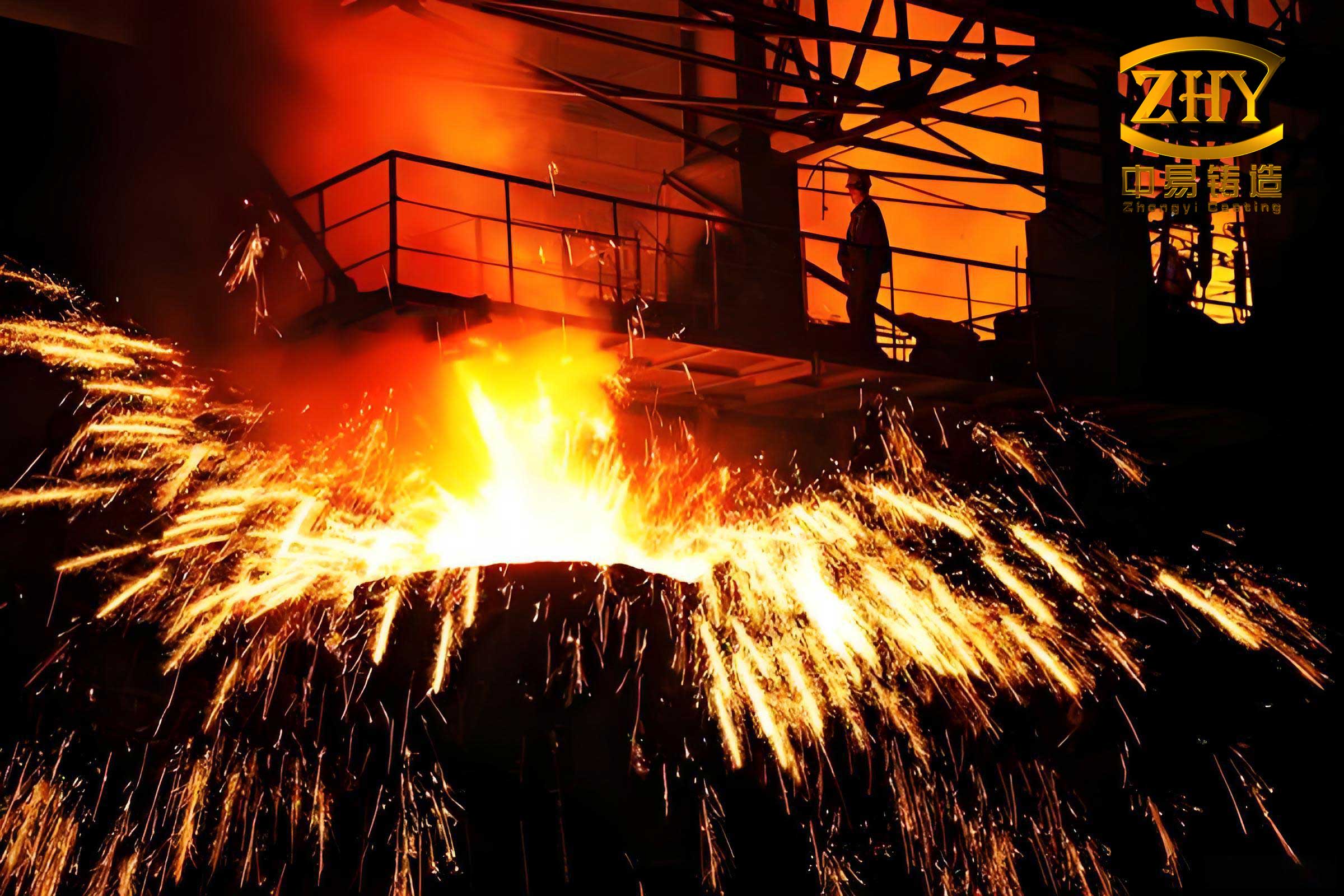
Ductile iron castings, such as this cylinder head, present unique challenges due to their complex geometries and performance requirements. The cylinder head, with external dimensions of approximately 623 mm × 418 mm × 275 mm in machined form and a rough weight of 210 kg, features intricate internal passages for water, oil, and gas. These ducts must be leak-proof, necessitating precise control over the casting process. The material specification, QT500-7, demands a minimum tensile strength of 500 MPa and elongation of 7% from samples taken at the combustion chamber plane, with a nodularity exceeding 90% and sulfur content below 0.018%. Achieving these properties in ductile iron castings requires a holistic approach, from pattern design to melting and pouring.
The complexity of ductile iron castings like this cylinder head arises from several factors. First, the internal cores are almost entirely surrounded by molten metal during pouring, making core support and venting critical to avoid defects such as gas holes or core floatation. Second, significant variations in wall thickness—with thick sections up to six or seven times thicker than thin ones—create isolated hot spots prone to shrinkage porosity. Third, the high integrity requirements for leak-tightness mean that any internal defect can lead to rejection. Through detailed process design, we can overcome these challenges and produce high-quality ductile iron castings.
Structural Analysis and Design Philosophy for Ductile Iron Castings
In designing the casting process for ductile iron castings, a thorough structural analysis is essential. The cylinder head consists of multiple cavities, including water jackets, valve ports, and bolt holes, all interconnected in a compact space. Using 3D modeling software, we identified critical areas such as the combustion chamber plane, valve guide holes, and injector bores, which require optimal solidification and feeding. For ductile iron castings, the graphite expansion during solidification can aid in self-feeding, but proper cooling control is necessary to prevent shrinkage. The design philosophy centers on ensuring directional solidification toward feeders and using chills to accelerate cooling in thick sections.
To quantify the geometry, we calculated the volume-to-surface area ratios for different sections, which influence cooling rates. For a section with thickness \( t \), the solidification time \( t_s \) can be estimated using Chvorinov’s rule:
$$ t_s = k \left( \frac{V}{A} \right)^n $$
where \( V \) is the volume, \( A \) is the surface area, \( k \) is a constant dependent on mold material, and \( n \) is an exponent typically around 2 for sand molds. For ductile iron castings, we adjust this based on the nodular graphite effect. Table 1 summarizes key dimensions and thermal characteristics of critical sections.
| Section | Thickness (mm) | Volume (cm³) | Surface Area (cm²) | V/A Ratio (cm) | Estimated Solidification Time (s) |
|---|---|---|---|---|---|
| Combustion Chamber Wall | 15 | 1200 | 800 | 1.50 | 180 |
| Injector Boss | 25 | 950 | 500 | 1.90 | 220 |
| Valve Guide Area | 20 | 800 | 450 | 1.78 | 200 |
| Indicator Valve Mount | 62 | 5200 | 1200 | 4.33 | 350 |
This analysis guides the placement of feeders and chills. For ductile iron castings, the goal is to achieve a progressive solidification pattern where thinner sections solidify first, feeding thicker ones through controlled expansion.
Pattern Making and Core Design for Ductile Iron Castings
Pattern and core design are crucial for producing accurate ductile iron castings. Given the production volume and complexity, we opted for metal patterns and a combination of machine-made and hand-made cores. The molding process uses furan resin sand for the mold and cores, but for the upper and lower water jacket cores, which have intricate shapes, we employed cold-box process cores made with a core shooter to ensure dimensional stability. This approach is common in high-quality ductile iron castings to reduce variability.
The core assembly for this cylinder head involves 16 different cores, categorized into internal cavity cores and external fill cores. Internal cores include the lower water jacket, small water jacket, upper water jacket, bolt holes, injector holes, pushrod chamber, and intake/exhaust ports. Each core is designed with adequate prints for support and venting. For instance, the pushrod chamber core has enlarged prints on one side for stability, while the exhaust port core extends prints to the mold exterior for secure fixing. External fill cores, such as side and end fill cores, are used to minimize fins and improve surface finish on non-critical areas of ductile iron castings.
Core venting is a critical aspect for ductile iron castings, as trapped gas can cause blowholes. We designed vent channels in each core, connected to the mold’s venting system via fiber tubes. The vent area \( A_v \) for a core can be estimated based on the gas generation rate during pouring:
$$ A_v = \frac{Q_g}{v_g} $$
where \( Q_g \) is the gas flow rate (dependent on core binder decomposition) and \( v_g \) is the allowable gas velocity. For typical resin-bonded sands in ductile iron castings, \( Q_g \) ranges from 0.1 to 0.3 L/s per kg of sand, and \( v_g \) is kept below 0.5 m/s to prevent metal penetration. Table 2 lists core details and venting specifications.
| Core Name | Material | Volume (dm³) | Vent Channel Diameter (mm) | Vent Area (cm²) | Connection Method |
|---|---|---|---|---|---|
| Lower Water Jacket | Cold-box Sand | 12.5 | 15 | 1.77 | Fiber Tube to Mold |
| Upper Water Jacket | Cold-box Sand | 10.8 | 12 | 1.13 | Fiber Tube to Mold |
| Pushrod Chamber | Furan Sand | 8.2 | 10 | 0.79 | Direct Print Vent |
| Exhaust Port | Furan Sand | 3.5 | 8 | 0.50 | Extended Print |
| Intake Port | Furan Sand | 3.2 | 8 | 0.50 | Extended Print |
During core assembly, we use checking fixtures to ensure precise positioning, which is vital for maintaining uniform wall thickness in the internal passages of ductile iron castings. Misalignment can lead to leakage paths or even穿孔, resulting in scrapped parts.
Gating System Design for Ductile Iron Castings
The gating system for ductile iron castings must ensure smooth filling, minimize turbulence, and prevent slag inclusion. For this cylinder head, we designed a bottom-gating system with two sides to distribute metal evenly. Each side features a downsprue, horizontal runner, and multiple ingates, with ceramic filters placed at the junction to trap impurities. This design is particularly effective for ductile iron castings, as it reduces oxidation and promotes laminar flow.
The gating dimensions were determined based on empirical data and fluid dynamics principles. The total ingate area \( A_g \) is calculated using the formula:
$$ A_g = C \cdot \sqrt{W} $$
where \( W \) is the casting weight (210 kg) and \( C \) is a coefficient ranging from 0.6 to 1.0 for ductile iron castings, depending on complexity. We used \( C = 0.8 \), giving \( A_g = 0.8 \times \sqrt{210} \approx 11.6 \, \text{cm}^2 \). However, to account for the complex geometry and ensure adequate feeding, we increased this to 16.0 cm². The gating ratio was set at \( A_g : A_r : A_s : A_d = 1 : 1.8 : 1.2 : 1.2 \), where \( A_r \) is the runner area, \( A_s \) is the sprue area, and \( A_d \) is the downsprue area. This yields \( A_r = 28.8 \, \text{cm}^2 \), \( A_s = 19.2 \, \text{cm}^2 \) per branch (two branches total), and \( A_d = 19.6 \, \text{cm}^2 \). The ingates are placed at 12 locations along the lower water jacket core, corresponding to M36 bolt holes, to introduce metal at multiple points and reduce thermal gradients.
The filling time \( t_f \) is estimated using the Bernoulli equation:
$$ t_f = \frac{V_c}{A_g \cdot v} $$
where \( V_c \) is the casting volume (approximately 0.027 m³ for ductile iron castings with a density of 7000 kg/m³) and \( v \) is the flow velocity, typically 0.5-1.0 m/s for ductile iron to avoid erosion. With \( v = 0.6 \, \text{m/s} \), we get \( t_f \approx 25 \, \text{s} \), which aligns with our practical pouring time of 25-30 s. Table 3 summarizes the gating system parameters.
| Component | Number | Cross-Sectional Area (cm²) | Dimensions (mm) | Function |
|---|---|---|---|---|
| Downsprue | 1 | 19.6 | Diameter: 50 | Vertical Flow |
| Branch Sprue | 2 | 19.2 each | Diameter: 35 | Distribution |
| Runner | 2 | 28.8 each | Rectangular: 60×48 | Slag Trapping |
| Ingate | 12 | 16.0 total | Each: 20×6.7 | Metal Entry |
| Filter | 2 | 25.0 each | Ceramic Disc | Impurity Removal |
This gating design has proven effective in producing sound ductile iron castings with minimal slag inclusion and controlled filling.
Riser and Chill Design for Ductile Iron Castings
Risers and chills are essential for managing solidification in ductile iron castings. Due to the graphite expansion, ductile iron can be less prone to shrinkage than gray iron, but isolated hot spots still require feeding. We placed a single blind riser (130 mm × 130 mm) on the top face of the casting, with two necks to feed the rocker arm mounting areas. Additionally, three vent risers (35 mm × 10 mm) were added to release gas and act as secondary feeders.
The riser size is based on the modulus method, where the riser modulus \( M_r \) should be greater than the casting modulus \( M_c \) by a factor of 1.2 to 1.5 for ductile iron castings. The modulus is defined as volume divided by cooling surface area. For the thickest section (indicator valve mount), \( M_c \approx 4.33 \, \text{cm} \) from Table 1, so \( M_r \) should be at least 5.2 cm. For a cylindrical riser with diameter \( D \) and height \( H = 1.5D \), the modulus is approximately \( D/6 \). Solving \( D/6 = 5.2 \) gives \( D = 31.2 \, \text{cm} \), but we used a square riser for practicality, with equivalent modulus.
Chills are used to accelerate cooling in thick sections and promote directional solidification. For this cylinder head, we inserted two internal chills (直径30 mm steel rods) at the indicator valve location and external chills (35 mm thick steel plates) at the bottom and fire face. At the valve guide holes, we used four shaped external chills. The chill design considers the heat extraction capacity, which can be modeled using Fourier’s law:
$$ Q = k \cdot A \cdot \frac{\Delta T}{d} $$
where \( Q \) is heat flux, \( k \) is thermal conductivity of the chill material (50 W/m·K for steel), \( A \) is contact area, \( \Delta T \) is temperature difference between metal and chill, and \( d \) is chill thickness. For ductile iron castings poured at 1400°C, with a chill initial temperature of 25°C, the heat extraction can be significant. Table 4 lists chill details.
| Location | Type | Dimensions (mm) | Material | Contact Area (cm²) | Estimated Heat Extraction (kJ) |
|---|---|---|---|---|---|
| Indicator Valve | Internal Chill | Diameter: 30, Length: 160 | Steel | 150 | 850 |
| Indicator Valve Base | External Chill | Thickness: 35, Area: 200×150 | Steel | 300 | 1700 |
| Fire Face | External Chill | Thickness: 35, Area: 180×120 | Steel | 216 | 1200 |
| Valve Guide Holes | Shaped External Chill | Custom Fit | Steel | 80 (each) | 450 (each) |
These chills help reduce the solidification time in hot spots, ensuring dense ductile iron castings free from shrinkage defects.
Process Parameters and Pattern Design for Ductile Iron Castings
Process parameters such as shrinkage allowance, machining allowances, and core clearances are critical for dimensional accuracy in ductile iron castings. Based on our experience with similar ductile iron castings, we applied a linear shrinkage of 0.9% to account for the contraction during cooling. Machining allowances were set at 7 mm for the top face, 5 mm for the bottom plane and process holes, and 6 mm per side for the injector holes. Small holes like valve guide holes below 28 mm diameter were not cored out to simplify the process.
Core prints were designed with a clearance of 0.4 mm to facilitate assembly while preventing metal penetration. Coatings were applied to cores: 0.6 mm per side for intake and exhaust ports to improve surface finish and prevent burn-on, and 0.4 mm for non-machined surfaces. Machined surfaces were left uncoated. The pattern was constructed from metal, with dimensions adjusted for these allowances. The design ensured that all cores fit precisely, which is vital for leak-tight ductile iron castings.
The overall process can be summarized using a quality function deployment (QFD) approach, linking customer requirements to process controls. For ductile iron castings, key requirements include mechanical properties, leak-tightness, and dimensional accuracy. We derived control parameters such as gating ratio, chill size, and pouring temperature. A simplified relationship can be expressed as:
$$ P = f(G, C, T) $$
where \( P \) represents performance metrics (e.g., tensile strength), \( G \) is gating design, \( C \) is chill application, and \( T \) is thermal parameters. Through iterative design, we optimized these factors for ductile iron castings.
Core Assembly and Venting in Ductile Iron Castings
Core assembly is a meticulous step in producing ductile iron castings. With 16 cores, alignment is checked using fixtures that verify critical dimensions like wall thickness between water jackets and ports. Any deviation can cause uneven walls or even penetration, leading to scrap. We developed a sequence for core setting: start with the lower water jacket core, then add internal cores, followed by external fill cores, and finally the upper mold.
Venting is integrated into the assembly. Each core has vent channels that connect to the mold’s venting system via fiber tubes. For example, the lower water jacket core has vents at the side prints, which are routed to the mold’s bottom vents. To prevent metal ingress, we seal the vent exits with adhesive before closing the mold. The venting efficiency \( \eta_v \) can be estimated as:
$$ \eta_v = \frac{A_{v,effective}}{A_{v,total}} \times 100\% $$
where \( A_{v,effective} \) is the unobstructed vent area. For our ductile iron castings, we aim for \( \eta_v > 95\% \) to ensure gas escape. Post-assembly, we perform a visual inspection and sometimes use compressed air to test vent flow.
This attention to detail in core handling is what sets high-quality ductile iron castings apart from average ones.
Melting and Metallurgy for Ductile Iron Castings
The melting process for ductile iron castings focuses on achieving precise chemistry and proper nodularization. We use medium-frequency induction furnaces to melt high-purity charge materials: low-sulfur pig iron and carbon steel scrap. This minimizes impurities that could degrade the properties of ductile iron castings. To enhance pearlite content and stabilize mechanical properties, we add 0.20% to 0.35% copper. The target chemistry for the melt and final casting is shown in Table 5.
| Element | Melt Range | Casting Range | Specification Limit | Role in Ductile Iron Castings |
|---|---|---|---|---|
| Carbon (C) | 3.4–3.8 | 3.3–3.8 | – | Graphite Formation, Fluidity |
| Silicon (Si) | 1.1–1.6 | 2.0–2.6 | – | Ferrite Strengthener, Inoculant |
| Manganese (Mn) | 0.25–0.45 | 0.25–0.45 | – | Pearlite Promoter |
| Phosphorus (P) | ≤0.07 | ≤0.07 | – | Impurity Control |
| Sulfur (S) | ≤0.025 | ≤0.018 | ≤0.018 | Nodularity Control |
| Copper (Cu) | 0.20–0.35 | 0.20–0.35 | – | Pearlite Stabilizer |
The melting temperature is maintained at 1510–1550°C to ensure complete dissolution and homogeneity. For treatment, we use a sandwich method: 1.2–1.4% nodularizer (magnesium-ferrosilicon alloy, 8–25 mm size) is placed at the bottom of the pouring ladle, covered with steel scrap, and then the molten iron is poured at 1470–1490°C. This promotes magnesium recovery and nodular graphite formation in ductile iron castings. Inoculation follows with 0.5–0.8% 75% ferrosilicon (3–20 mm size) to enhance graphite nucleation. The nodularity \( N \) can be estimated from the residual magnesium content \( Mg_{res} \) using an empirical relation:
$$ N (\%) = 80 + 10 \times (Mg_{res} – 0.03) $$
where \( Mg_{res} \) is typically 0.04–0.06% for ductile iron castings. We aim for \( N > 90\% \), as required.
The kinetics of nodularization can be described by a first-order reaction model:
$$ \frac{d[Mg]}{dt} = -k [Mg] $$
where \( k \) is a rate constant dependent on temperature and ladle geometry. By controlling these parameters, we consistently achieve high-quality ductile iron castings.
Pouring and Solidification of Ductile Iron Castings
Pouring is conducted with strict protocols to ensure the integrity of ductile iron castings. The molds are placed on a porous bed to allow bottom venting, and pouring is done quickly but steadily to maintain the designed filling time. A operator skims slag and ignites gases at the vents to prevent air aspiration. The pouring temperature is critical; we use 1380–1400°C for ductile iron castings to balance fluidity and shrinkage. Lower temperatures can cause misruns, while higher ones increase gas solubility and mold erosion.
During solidification, we monitor the cooling curve using thermocouples embedded in the mold. For ductile iron castings, the cooling curve shows characteristic plateaus due to graphite precipitation. The solidification progress \( f_s \) as a function of time \( t \) can be modeled as:
$$ f_s = 1 – \exp\left(-b (t – t_0)^n\right) $$
where \( b \) and \( n \) are constants, and \( t_0 \) is the start time. This helps predict shrinkage tendencies and adjust riser efficiency. After pouring, the castings are left in the mold until they reach below 500°C to avoid cracking, then shaken out and cleaned.
The entire process, from melting to shakeout, is controlled to produce reliable ductile iron castings.
Results and Validation for Ductile Iron Castings
We produced 25 cylinder heads in two batches using the described process. All ductile iron castings were inspected non-destructively (visual, penetrant testing) and then sectioned for internal quality checks. The sections revealed no shrinkage porosity or gas holes, with uniform wall thickness in internal passages. Machining trials confirmed dimensional accuracy and leak-tightness under pressure tests.
Mechanical testing from the combustion chamber plane showed tensile strength averaging 520 MPa, elongation 8%, and nodularity above 92%, exceeding specifications. The success of these ductile iron castings demonstrates the effectiveness of our integrated approach. Table 6 summarizes the test results.
| Batch | Tensile Strength (MPa) | Elongation (%) | Nodularity (%) | Defect Rate (%) | Leak Test Result |
|---|---|---|---|---|---|
| 1 | 515–525 | 7.5–8.5 | 91–93 | 0 | Pass |
| 2 | 518–530 | 8.0–9.0 | 92–94 | 0 | Pass |
These ductile iron castings have been approved for mass production, validating our process design.
Conclusions and Future Directions for Ductile Iron Castings
In summary, producing high-integrity ductile iron castings like cylinder heads requires a comprehensive strategy encompassing design, process control, and metallurgy. Key takeaways include: (1) Using chills in thick sections effectively prevents shrinkage in ductile iron castings by accelerating cooling. (2) A filtered, bottom-gating system ensures clean, tranquil filling for ductile iron castings. (3) Precise core assembly with adequate venting avoids gas defects in ductile iron castings. (4) Controlled melting and treatment yield consistent mechanical properties in ductile iron castings.
For future work, we are exploring simulation software to optimize feeder and chill placements for ductile iron castings, reducing trial-and-error. Additionally, we are investigating alloy additions like nickel or molybdenum to enhance the performance of ductile iron castings in even more demanding applications. The continuous improvement of ductile iron castings remains a focus for advancing engine technology.
Through this case study, I hope to convey that meticulous attention to every detail—from pattern to pour—is essential for excellence in ductile iron castings. The synergy of engineering principles and practical foundry skills enables us to meet the evolving challenges of modern manufacturing.