
In the realm of manufacturing, foundry technology plays a pivotal role in producing high-quality cast components, especially for precision machinery. As a foundry engineer with extensive experience, I have been involved in numerous projects where innovative foundry technology was essential to overcome challenges in casting complex parts. One such project focused on the production of a bed casting for an internal grinding machine, which demanded exceptional dimensional accuracy, internal quality, and specific hardness requirements in critical areas like the guide rails. This article delves into the comprehensive application of foundry technology to address these demands, leveraging detailed process design, material science, and empirical validation. Through this first-person account, I will share insights into how advanced foundry technology enabled the successful production of these castings, emphasizing the use of tables and formulas to summarize key aspects. The integration of modern foundry technology not only ensured compliance with specifications but also minimized defects, showcasing the transformative power of systematic approaches in metal casting.
The bed casting, as a core component of the grinding machine, exhibits a intricate internal structure with numerous ribs and cavities that house hydraulic cylinders and rack mechanisms. Its design includes a rectangular frame for cutting fluid recovery, a curved bottom surface for efficient drainage, and two guide rails—a flat one and a triangular one—that require a hardness exceeding 180 HBW to ensure wear resistance. With a weight of approximately 190 kg and made of HT 200 gray iron, the casting measures 1350 mm in length, 300 mm in width, and 100 mm in height, featuring a maximum wall thickness of 45 mm and a minimum of 12 mm. Such disparities in wall thickness pose significant challenges in foundry technology, as achieving high hardness in thick sections without inducing brittleness in thin areas is critical. The following sections elaborate on the foundry technology employed, from initial analysis to final validation, highlighting how each step contributed to a defect-free outcome.
To begin, the casting process was meticulously planned based on the principles of foundry technology. The pouring position was selected with the guide rails facing downward, adhering to the fundamental rule of placing critical surfaces in the lower part of the mold to minimize defects like slag inclusions and gas porosity. This orientation also facilitated the placement of cores for the internal cavities. The parting line was established along the mold joint, and split-pattern molding was adopted using pattern plates to enhance dimensional stability and reduce distortion. Dry sand molds and cores were employed to withstand the thermal stresses during pouring, a common practice in advanced foundry technology for high-integrity castings. The pattern plates incorporated pre-formed elements for narrow sections, such as the upper and lower edges, as well as integrated gating system components like runners and slag traps, ensuring consistency and durability. Key casting parameters were defined through empirical formulas and historical data, as summarized in Table 1.
| Parameter | Value | Description |
|---|---|---|
| Machining Allowance (Top Surface) | 7.5 mm | To eliminate potential defects in upper regions |
| Machining Allowance (Guide Rails and Sides) | 5 mm | Minimized due to lower defect probability |
| Shrinkage Rate | 1% | Accounted for patternmaker’s shrinkage |
| Draft Angle | 1° | Facilitates pattern removal |
| Parting Line Allowance | 1 mm | Compensates for mold joint inaccuracies |
| Core Print Allowance | 1 mm | Ensures proper core seating and alignment |
The core design was a critical aspect of the foundry technology, as the internal cavities required precise dimensions for component assembly. Four cores were utilized: two main cores (designated as 1# and 2#) forming the longitudinal internal cavity, a drainage port core (4#), and a small core (3#) for an end hole. The main cores, each 1320 mm long, were split for ease of manufacturing and handling. They were reinforced with specialized core reinforcements to prevent breakage in thin sections, and coke was incorporated into the core mass to enhance gas venting. After coating with lead-based paint and drying, the cores were assembled in the mold, with vent holes aligned to allow gases to escape during pouring. This meticulous core design underscores the importance of integrated foundry technology in achieving dimensional accuracy and internal soundness.
The gating and risering system was engineered based on foundry technology principles to ensure smooth metal flow and effective slag removal. A gating system with a centrifugal slag trap was adopted, characterized by a ratio of cross-sectional areas: ∑Finner : ∑Frunner : ∑Fsprue = 1 : 1.6 : 1.25. Calculations for the inner gate area yielded a value of 7.6 cm², leading to the design of two inner gates with dimensions of 28 mm / 34 mm × 12 mm, positioned at the casting ends to direct flow toward the guide rails. The runner, with a total cross-section of 6.1 cm² (20 mm / 24 mm × 28 mm), included a centrifugal slag trap of dimensions φ55 mm / φ65 mm × 65 mm to capture inclusions. A single sprue of 35 mm diameter (∑Fsprue = 9.6 cm²) was placed centrally. Additionally, two open risers, each φ70 mm × 200 mm, were positioned on the thick rectangular bosses to mitigate shrinkage defects and facilitate gas escape. The design can be represented mathematically using fluid dynamics principles; for instance, the flow rate Q through the gating system can be approximated by $$Q = A \cdot v$$ where A is the cross-sectional area and v is the velocity, which depends on the head height and friction losses. This approach in foundry technology ensures optimal feeding and minimizes turbulence.
Venting strategies are indispensable in foundry technology to prevent gas-related defects. For the mold cavity, vent holes were drilled at the highest points, such as along the upper edges and on process bosses, to allow trapped gases to escape. For the cores, the main cores included coke inserts connected to vent passages through the core prints. These vents were sealed with oil clay to prevent metal infiltration, ensuring continuous gas flow to the exterior. This dual venting mechanism highlights how comprehensive foundry technology addresses both mold and core gas evolution, crucial for producing sound castings.
Material composition is a cornerstone of foundry technology, directly influencing mechanical properties and castability. For the HT 200 gray iron, the chemical composition was carefully controlled to balance hardness and machinability. The carbon equivalent (CE) is a key parameter, calculated as $$CE = C + \frac{1}{3}(Si + P)$$ where C, Si, and P are the weight percentages of carbon, silicon, and phosphorus, respectively. To achieve the desired hardness in thick sections without causing chilling in thin walls, a lower silicon-to-carbon ratio was initially considered, but adjustments were made to enhance inoculant effectiveness. The base iron had a silicon content of 1.4–1.7%, and after inoculation with 75% ferrosilicon in the ladle, the final composition was optimized as shown in Table 2. This treatment, a standard practice in foundry technology, promoted graphitization and improved the hardness uniformity across varying wall thicknesses.
| Element | Weight Percentage (%) | Role in Foundry Technology |
|---|---|---|
| Carbon (C) | 3.2–3.4 | Enhances fluidity and reduces shrinkage |
| Silicon (Si) | 1.6–2.0 | Promotes graphitization and strength |
| Manganese (Mn) | 0.7–0.9 | Neutralizes sulfur and improves hardness |
| Sulfur (S) | < 0.15 | Minimized to prevent hot tearing |
| Phosphorus (P) | ≤ 0.12 | Limited to avoid brittleness |
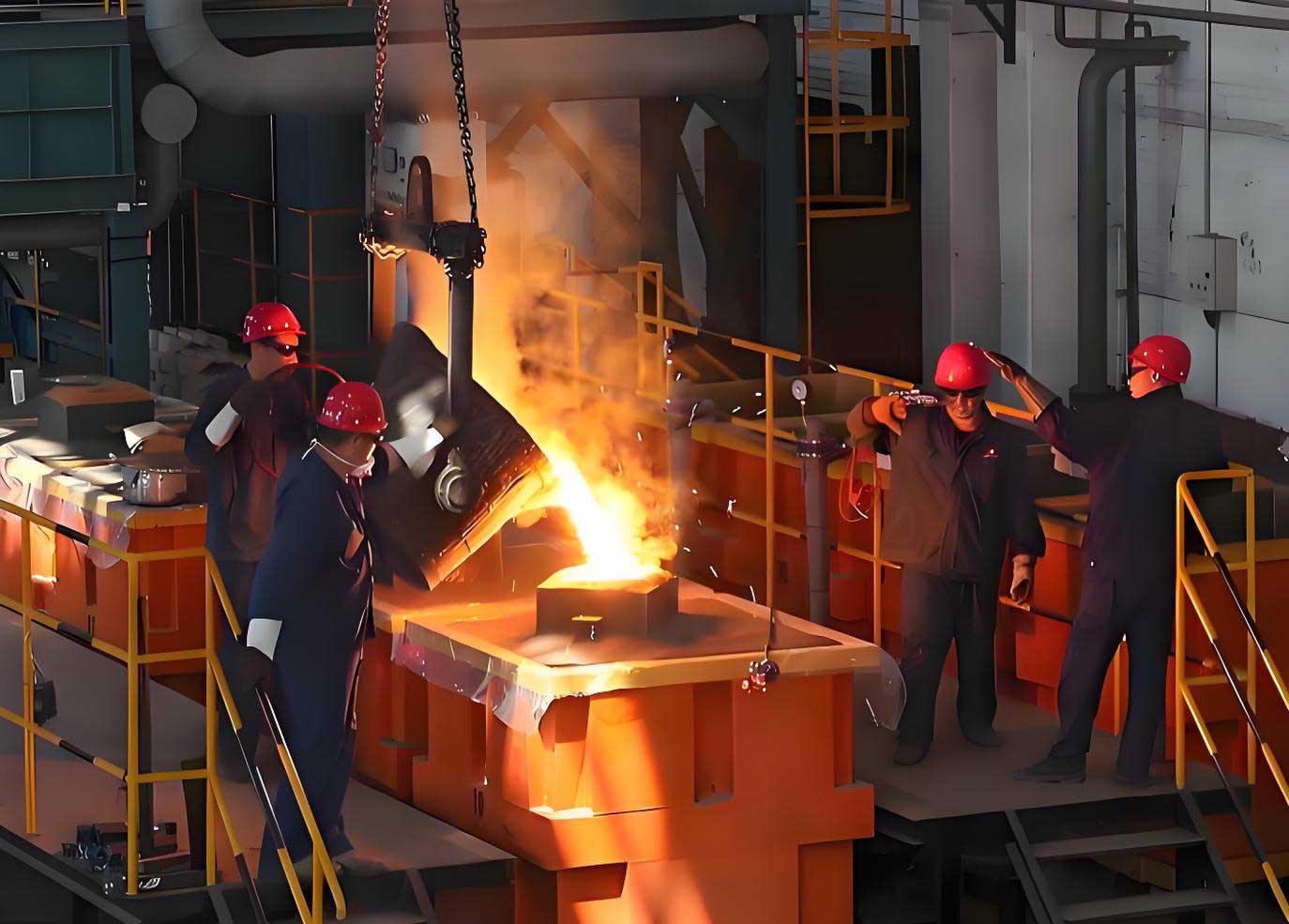
The production validation phase involved a batch of 20 castings, where foundry technology was applied rigorously. Pattern plates and molding boxes were prepared according to specifications, and the molds and cores were coated, dried, and assembled. Core supports were used to secure the cores, and the mold was closed after thorough inspection. Melting was conducted in an acid cupola, with a tap temperature of 1490°C. Inoculation was performed using 75% ferrosilicon, and the melt was tested with wedge samples to assess chilling tendency, showing a white iron depth of 6 mm. Pouring was carried out at 1440°C over 46 seconds, with careful slag skimming and ignition of evolved gases. After cooling, the castings were shaken out, and the gating systems and fins were removed. This systematic execution demonstrates how foundry technology integrates process control to achieve consistent results.
Inspection results confirmed the efficacy of the applied foundry technology. Among the 20 castings, one was scrapped due to visible gas porosity, resulting in a scrap rate of 5%. Hardness tests on the guide rails of the remaining 19 castings showed values between 182 and 203 HBW, meeting the requirement of over 180 HBW. Dimensional checks revealed that all shape and size tolerances were within specified limits. During machining and scraping of the guide rails, the metal exhibited a dense structure and desirable metallic luster, with no issues of brittleness in thinner sections. Subsequent production batches maintained this scrap rate below 5%, underscoring the reliability of the foundry technology implemented. The relationship between hardness and composition can be modeled using empirical equations, such as $$HBW = k_1 \cdot C + k_2 \cdot Si + k_3 \cdot Mn + c$$ where k1, k2, k3 are coefficients and c is a constant, derived from regression analysis of historical data. This formula exemplifies how foundry technology leverages mathematical models to predict material behavior.
In conclusion, the successful production of the bed casting for the internal grinding machine exemplifies the advancements in foundry technology. By addressing challenges such as wall thickness variations and high hardness requirements through meticulous process design, including optimized gating, core venting, and material composition, this project highlights how foundry technology can achieve defect-free castings with consistent properties. The use of tables and formulas throughout this account not only summarizes key parameters but also provides a framework for replicating such successes in other applications. As foundry technology continues to evolve, incorporating simulation and real-time monitoring, it will further enhance the precision and efficiency of casting processes. This experience reinforces my belief that a deep understanding of foundry technology is indispensable for overcoming complex manufacturing hurdles and delivering high-performance components.