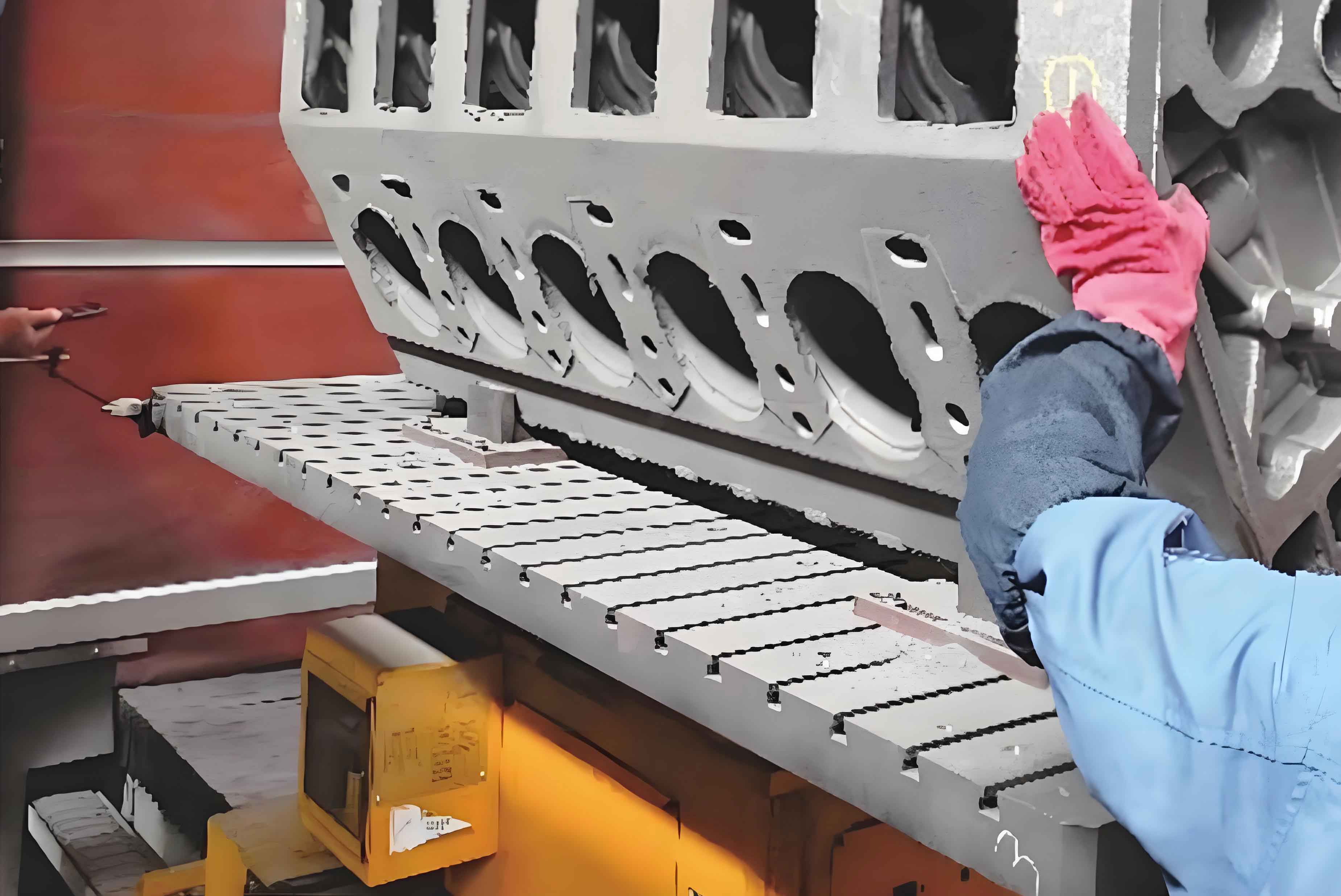
Modern manufacturing of engine cylinder block bores requires systematic optimization of machining processes to achieve dimensional accuracy within ±0.005 mm and surface roughness below Ra 0.4 μm. This article presents a comprehensive analysis of machining strategies, process parameters, and quality control measures for engine cylinder block production.
1. Machining Process Architecture
The manufacturing sequence for engine cylinder blocks follows three critical phases:
| Process Stage | Tolerance (mm) | Surface Roughness (Ra) | Cycle Time (min) |
|---|---|---|---|
| Rough Boring | ±0.15 | 6.3 μm | 12.5 |
| Semi-Finishing | ±0.03 | 3.2 μm | 8.2 |
| Finish Honing | ±0.005 | 0.4 μm | 6.8 |
The material removal rate (MRR) during rough boring can be calculated using:
$$ MRR = \frac{\pi \cdot D \cdot f \cdot a_p}{1000} $$
Where:
D = Bore diameter (mm)
f = Feed rate (mm/rev)
ap = Cutting depth (mm)
2. Cutting Parameter Optimization
Optimal parameters for engine cylinder block machining:
| Tool Type | Cutting Speed (m/min) | Feed Rate (mm/rev) | Depth of Cut (mm) |
|---|---|---|---|
| PCD Insert | 180-240 | 0.12-0.18 | 0.25 |
| CBN Wheel | 35-45 | 0.02-0.05 | 0.01 |
The thermal deformation compensation formula for engine cylinder blocks during machining:
$$ \Delta D = \alpha \cdot D_0 \cdot (T_m – T_a) $$
Where:
α = Thermal expansion coefficient (11.7×10⁻⁶/°C for aluminum)
D0 = Nominal bore diameter
Tm = Machining temperature
Ta = Ambient temperature
3. Surface Integrity Control
Critical parameters for engine cylinder block bore surface finishing:
| Parameter | Roughing | Finishing | Superfinishing |
|---|---|---|---|
| Surface Roughness Ra | 3.2-6.3 μm | 0.8-1.6 μm | 0.1-0.4 μm |
| Roundness Error | 15-25 μm | 5-8 μm | 1-2 μm |
| Cylindricity | 20-30 μm | 8-12 μm | 2-3 μm |
The surface roughness prediction model for engine cylinder block honing:
$$ R_a = K \cdot \frac{v_f^{1.2}}{v_c^{0.8} \cdot p^{0.5}} $$
Where:
K = Material constant
vf = Feed speed
vc = Cutting speed
p = Honing pressure
4. Process Innovation Case Study
A automotive manufacturer achieved 40% cycle time reduction in engine cylinder block production through:
| Improvement | Before | After | Gain |
|---|---|---|---|
| Tool Life | 150 pcs | 220 pcs | +46.7% |
| Bore Diameter Variation | ±0.015 mm | ±0.006 mm | 60% reduction |
| Surface Roughness | Ra 0.8 μm | Ra 0.35 μm | 56% improvement |
The optimized cutting force equation for engine cylinder block machining:
$$ F_c = K_c \cdot a_p \cdot f \cdot \left(\frac{v_c}{v_{ref}}\right)^{m} $$
Where:
Kc = Specific cutting force
vref = Reference cutting speed
m = Material exponent
5. Thermal Management Strategy
Critical cooling parameters for engine cylinder block machining stability:
| Coolant Type | Flow Rate (L/min) | Pressure (bar) | Temperature Control |
|---|---|---|---|
| Synthetic Emulsion | 45-60 | 10-15 | ±2°C |
| High-Pressure Mist | 8-12 | 40-60 | ±1.5°C |
| Cryogenic CO2 | 3-5 | N/A | -78°C |
The temperature rise model in engine cylinder block machining:
$$ \Delta T = \frac{P_c \cdot t}{m \cdot c_p} $$
Where:
Pc = Cutting power
t = Cutting time
m = Workpiece mass
cp = Specific heat capacity
6. Precision Measurement Systems
Advanced metrology solutions for engine cylinder block quality assurance:
| Measurement Type | Accuracy | Repeatability | Speed |
|---|---|---|---|
| Laser Scanning | ±0.5 μm | 0.3 μm | 15 sec/bore |
| Air Gaging | ±1.0 μm | 0.8 μm | 8 sec/bore |
| Multi-sensor CMM | ±0.8 μm | 0.5 μm | 25 sec/bore |
The comprehensive quality index (CQI) for engine cylinder block evaluation:
$$ CQI = \sqrt{\frac{(D_a – D_t)^2}{D_t^2} + \left(\frac{R_a}{R_{spec}}\right)^2 + \left(\frac{T_w}{T_{flat}}\right)^2} $$
Where:
Da = Actual diameter
Dt = Target diameter
Rspec = Roughness specification
Tw = Wall thickness variation
Tflat = Flatness tolerance
