
In the global pursuit of sustainable energy, wind power has emerged as a pivotal clean and renewable source, garnering widespread attention and investment. Among the critical components of wind turbine systems, shell castings such as gearbox housings, base frames, and bearing seats play an indispensable role. These ductile iron castings operate at elevated heights ranging from tens to over a hundred meters, enduring harsh environmental conditions, including temperatures as low as -20°C to -40°C, while maintaining structural integrity and performance for service lives exceeding 20 years. Consequently, these shell castings demand exceptionally high comprehensive performance metrics, necessitating rigorous quality control throughout the manufacturing process. In this article, I will elaborate on the production process and quality control measures for a 2 MW large-scale wind turbine hollow drive shell casting, drawing from extensive industrial experience and research. The focus will be on overcoming inherent challenges through meticulous casting design, precise chemical composition management, and optimized melting, spheroidization, and inoculation treatments.
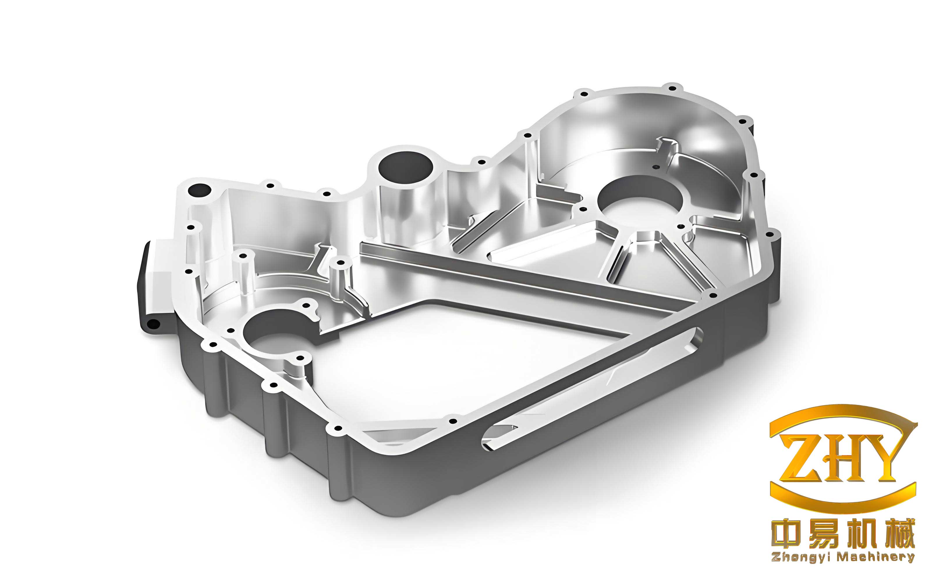
The production of high-integrity shell castings for wind turbines involves navigating numerous technical hurdles, primarily due to the stringent performance requirements and complex geometries. The hollow drive shell casting under consideration features an outer contour dimensions of ϕ1,678 mm × ϕ800 mm × 743 mm, with a mass of 1,514 kg. Its structure is a truncated cone with a wall thickness of 40 mm, reinforcement ribs of 30 mm, and a maximum wall thickness of 70 mm. The material specification is EN-GJS-400-18U-LT, a ductile iron grade designed for low-temperature applications. Key difficulties arise from the need to meet exacting mechanical properties and microstructural standards per EN1563, which stipulate that Charpy V-notch impact energy at -20°C must be no less than 7 J for individual specimens and an average of 10 J for three specimens. Additionally, non-destructive testing mandates 100% ultrasonic and magnetic particle inspection, with internal quality conforming to Level 2 requirements of EN12680.3 and DIN EN1369. These demands compel the adoption of targeted strategies in casting process design and parameter optimization to ensure defect-free shell castings that fulfill all operational criteria.
To address these challenges, the casting process scheme was developed with a focus on precision, stability, and controllability. The initial step involves the design of the parting plane, which is crucial for dimensional accuracy and surface finish. Given that the machining allowances are 14 mm on the upper section, 12 mm on the lower and lateral sections, and 14 mm on holes, a cold-set furan resin sand was employed for molding and core-making across all components. This choice enhances mold stability and reduces thermal deformation. The parting plane position was optimized to facilitate easy mold assembly and ejection, as illustrated in conceptual layouts. Moreover, to prevent defects like sand sticking, scabbing, and sand inclusions, a zircon-based coating with a thickness of 0.4–0.6 mm was applied to mold and core surfaces, ensuring a smooth casting surface for these critical shell castings.
The core design is integral to forming the internal cavities of the hollow drive shell castings. Three distinct core types were utilized: one #1 core with dimensions ϕ734 mm × 530 mm and mass 236 kg; one #2 core with dimensions ϕ1,420 mm × ϕ516 mm × 552 mm and mass 1,109 kg; and six #3 lug hole cores, each measuring 100 mm × 70 mm × 70 mm with a mass of 0.5 kg. These cores were strategically positioned to create the complex internal geometry, with careful attention to core prints and vents to ensure proper seating and gas evacuation during pouring. The use of resin sand allows for precise core shaping and adequate collapsibility post-casting, minimizing stresses in the final shell castings.
The gating system design adheres to the principle of “large flow rate, low velocity, and smooth filling” to minimize turbulence and oxidation. For these shell castings, a semi-open bottom-gating system was implemented, employing a ceramic tube with an internal diameter of 70 mm as the sprue. The ingates are located at the large-end flange of the casting, introducing molten metal radially along the circumference to promote uniform filling. Additionally, nine ϕ15 mm vent holes are evenly distributed on the top surface, along with four ϕ80 mm edge feeders, to exhaust gases and float impurities. The gating ratio, after adjustments, is set at ΣFsprue : ΣFrunner : ΣFingate = 1 : 1.8 : 1.6, which ensures a balanced flow for the 1,514 kg pour. The filling process can be modeled using fluid dynamics principles, where the flow rate Q is given by: $$ Q = A \sqrt{2gh} $$ where A is the cross-sectional area, g is gravitational acceleration, and h is the metallostatic head. This equation helps in optimizing gating dimensions to achieve the desired fill time for shell castings.
Cooling system design is vital to control solidification and prevent shrinkage defects in thick-walled shell castings. Given the slow cooling inherent in furan resin sand molds, a combination of chills and enhanced cooling was adopted. Chills, with thicknesses equal to the local wall thickness (1.0 times), are placed at strategic locations to accelerate cooling in slower-solidifying regions. The layout includes multiple chill types, such as #1, #2, and #3 chills, arranged with 20 mm spacing to uniformize thermal gradients. The cooling rate can be approximated by Fourier’s law: $$ \frac{dT}{dt} = \alpha \nabla^2 T $$ where α is thermal diffusivity, and T is temperature. By increasing heat extraction via chills, the solidification time t is reduced, which is estimated using Chvorinov’s rule: $$ t = B \left( \frac{V}{A} \right)^2 $$ where V is volume, A is surface area, and B is a mold constant. This approach mitigates shrinkage porosity and enhances the metallurgical quality of shell castings.
| Element | Target Range | Role and Rationale |
|---|---|---|
| Carbon (C) | 3.65% – 3.80% | Enhances fluidity, promotes graphite precipitation, and reduces shrinkage defects. Excess can cause graphite flotation. |
| Silicon (Si) | 1.90% – 2.40% | Improves strength but must be limited for low-temperature toughness; high Si reduces ductility. |
| Manganese (Mn) | < 0.20% | Minimized to avoid carbide formation and segregation, which impair impact toughness. |
| Phosphorus (P) | < 0.02% | Kept low to prevent phosphide eutectics at grain boundaries, reducing brittleness. |
| Sulfur (S) | < 0.012% | Controlled to optimize spheroidization efficiency and reduce slag formation. |
| Rare Earth (RE) | 0.010% – 0.020% | Aids nodularization; excess can lead to degenerate graphite. |
| Magnesium (Mg) | 0.035% – 0.060% | Primary spheroidizing agent; residual levels are critical for graphite morphology. |
Melting and pouring practices are cornerstone to achieving the desired properties in shell castings. The duplex melting process involves an 18 t/h cupola and a 5 t medium-frequency induction furnace, with charge materials comprising 50–70% pig iron, 20–40% returns, and 10–20% scrap steel. High-purity pig iron is selected to limit trace elements, while returns and scrap are pre-processed to eliminate contaminants. Spheroidization is performed using the sandwich method in a ladle, with a magnesium-ferrosilicon alloy added at 1.0–1.2% of iron mass. A covering layer of 0.1% 3–8 mm inoculant and a pressure plate improve magnesium recovery by 20–30%. The reaction kinetics can be described by: $$ [\text{Mg}]_{\text{residual}} = [\text{Mg}]_{\text{added}} – k \cdot [\text{S}] $$ where k is a reaction constant, emphasizing the need for low sulfur levels in shell castings.
Inoculation is conducted in two stages to enhance graphite nucleation and prevent fading. Primary inoculation involves adding 0.3% FeSi75 (10–14 mm) during tapping, while secondary inoculation uses 0.2–0.3% fine-grained (1–3 mm) barium-silicon inoculant during transfer to a pouring ladle. This dual treatment refines graphite structure, as quantified by the nodule count N: $$ N = N_0 \exp(-t/\tau) $$ where N0 is initial nodule count, t is time, and τ is the fading constant. Pouring temperature is tightly controlled at 1,320 ± 10°C using a 2 t calibrated ladle with stopper rod, balancing fluidity and shrinkage tendencies. The thermal history during pouring affects solidification patterns, which is critical for integrity of shell castings.
| Property | Standard Requirement (EN1563) | Typical Achieved Value |
|---|---|---|
| Tensile Strength | ≥ 370 MPa | 404 MPa |
| Yield Strength | ≥ 230 MPa | 262 MPa |
| Elongation | ≥ 15.0% | 24.0% |
| Hardness (HB) | 120 – 175 | 144 |
| Charpy Impact (-20°C) | Individual ≥ 7 J, Avg. ≥ 10 J | 15, 14, 13 J (Avg. 14 J) |
| Graphite Nodularity | ≥ 90% | 95% |
| Graphite Size | 5 – 8 μm | 6 μm |
| Pearlite Content | ≤ 10% | < 5% |
| Ferrite Content | ≥ 90% | > 95% |
| Carbide Content | ≤ 1% | 0.5 – 1% |
Production validation involved manufacturing multiple units of the hollow drive shell castings, with thorough testing to confirm compliance. The castings exhibited excellent dimensional accuracy, surface finish, and internal soundness upon ultrasonic and magnetic particle inspection. Attached test bars (70 mm × 70 mm × 180 mm) were evaluated for microstructure and mechanical performance, revealing fully spheroidized graphite with high nodule counts and a predominantly ferritic matrix. The impact toughness values exceeded specifications, underscoring the efficacy of the low-temperature grade ductile iron formulation. These results demonstrate that the integrated approach—encompassing optimized gating, controlled cooling, precise chemistry, and robust treatment processes—can reliably produce high-quality shell castings for demanding wind turbine applications.
The quality control framework for shell castings extends beyond process parameters to include statistical monitoring and adaptive adjustments. For instance, the relationship between cooling rate and mechanical properties can be modeled using regression analysis: $$ \sigma_y = \sigma_0 + k_y \cdot \left( \frac{dT}{dt} \right)^{1/2} $$ where σy is yield strength, σ0 is a material constant, and ky is a strengthening coefficient. Similarly, the risk of shrinkage defects in shell castings is assessed via feeding efficiency metrics, such as the modulus method: $$ M = \frac{V}{A} $$ where higher modulus areas require adequate feeder design. By implementing real-time process controls and periodic audits, the consistency of shell castings is maintained across production batches.
In conclusion, the manufacturing of large wind turbine shell castings demands a holistic strategy that addresses every stage from design to pouring. Key successes stem from meticulous parting plane and core design, balanced gating systems, effective cooling with chills, stringent chemical control, and optimized spheroidization and inoculation. The repeated emphasis on shell castings throughout this process highlights their critical role in renewable energy infrastructure. Future advancements may involve computational simulations for solidification prediction and additive manufacturing for core production, further enhancing the reliability and sustainability of shell castings. By adhering to these principles, manufacturers can meet the escalating global demand for durable and efficient wind power components, contributing to a cleaner energy future.