
In my years of experience in quality supervision and product acceptance for diesel engines, I have encountered numerous challenges related to metal casting, forging, and welding technologies. Among these, the casting of ductile iron components, such as the upper crankcase for high-speed, high-power diesel engines, presents significant difficulties due to the inherent tendency for casting defects. These casting defects, particularly shrinkage porosity, can severely impact the integrity and performance of critical parts. This article delves into a detailed analysis of these casting defects, exploring their mechanisms, influencing factors, and the control measures necessary to ensure high-quality production.
The upper crankcase serves as the backbone of a diesel engine, enduring gas pressures, inertial forces from moving parts, pre-stresses from bolts, and complex spatial force systems. For a renowned series of high-performance diesel engines, the use of ductile iron for the upper crankcase enhances strength and reliability but introduces substantial casting and machining complexities. The prevalence of casting defects, especially shrinkage porosity, has historically led to issues like leakage during hydraulic testing, resulting in scrap parts and increased costs. This underscores the critical need to understand and mitigate these casting defects.
Casting defects in ductile iron are multifaceted, with shrinkage porosity being a predominant concern. Ductile iron, developed over the past few decades, offers a favorable combination of high strength, some elongation, and cost-effectiveness compared to steel. However, its solidification characteristics—specifically a wide mushy zone and significant eutectic expansion—predispose it to shrinkage porosity. These casting defects manifest as macroscopic voids that are visible to the naked eye, often located at thermal junctions or last-to-solidify areas of a casting, such as around bolt holes or thick sections.
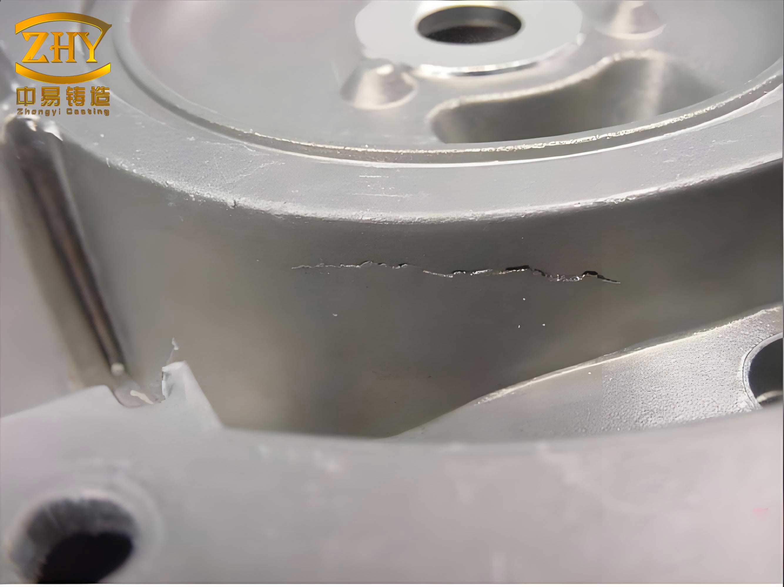
To quantify the issue, statistical data from a batch of 56 crankcases revealed a high incidence of casting defects. The table below summarizes the location and frequency of these casting defects:
| Defect Location | Number of Affected Castings | Primary Defect Type |
|---|---|---|
| Combined Face M12 Holes | 8 | Shrinkage Porosity |
| Lifter Body Holes | 7 | Shrinkage Porosity |
| Oil Passage Holes | 3 | Shrinkage Porosity |
| Cylinder Head M20 Bolt Holes | 2 | Shrinkage Porosity |
This concentration of casting defects highlights the need for a thorough investigation into their root causes. The material specification for these crankcases is QT500-7, requiring tensile strength ≥500 MPa, elongation ≥7%, and freedom from internal flaws like shrinkage cavities, cracks, or excessive porosity. Post-machining, 100% hydraulic testing is mandatory, with no leaks permitted, making the control of casting defects paramount.
The formation of shrinkage porosity, a key category of casting defects, is governed by the solidification and contraction behavior of ductile iron. The total volume of shrinkage porosity can be expressed by the following formula, which encapsulates the interplay of various factors:
$$ V_{\text{total shrinkage}} = V_{\text{liquid contraction}} + V_{\text{solidification contraction}} – V_{\text{graphite expansion}} + V_{\text{mold wall movement}} $$
Where:
- \( V_{\text{total shrinkage}} \) is the total volume of shrinkage porosity.
- \( V_{\text{liquid contraction}} \) is the volume contraction during the liquid phase.
- \( V_{\text{solidification contraction}} \) is the volume contraction during solidification.
- \( V_{\text{graphite expansion}} \) is the volume expansion due to graphite precipitation during eutectic transformation.
- \( V_{\text{mold wall movement}} \) is the additional volume from mold wall displacement.
In ductile iron, the graphite expansion (\( V_{\text{graphite expansion}} \)) is significant, approximately 4.2% from graphite precipitation, but the mushy solidification can block feeding channels, leading to net shrinkage and casting defects. Areas that are thermal centers or last to solidify, such as those identified in the table, are particularly prone to these casting defects.
Several factors influence the severity of casting defects, particularly shrinkage porosity. A primary factor is chemical composition. The table below outlines the critical ranges for molten iron composition to minimize casting defects:
| Element/Parameter | Raw Iron Target (%) | Treated Iron Target (%) | Impact on Casting Defects |
|---|---|---|---|
| Carbon (C) | 3.7 – 4.0 | 3.5 – 3.8 | Low C reduces graphite expansion; high C promotes floating graphite. |
| Silicon (Si) | 1.6 – 1.8 | 2.5 – 2.8 | Affects graphitization and strength. |
| Carbon Equivalent (CE) | 4.25 – 4.6 | 4.2 – 4.8 | Optimal range crucial to balance fluidity and shrinkage. |
| Phosphorus (P) | ≤0.06 | ≤0.06 | High P increases shrinkage tendency. |
| Sulfur (S) | ≤0.04 | ≤0.01 | |
| Residual Magnesium (Mg残) | – | 0.02 – 0.035 | Excessive Mg increases shrinkage porosity. |
| Residual Rare Earth (RE残) | – | 0.05 – 0.075 | High RE raises shrinkage tendency. |
Deviations from these ranges can exacerbate casting defects. For instance, low carbon equivalent reduces graphite expansion, while high sulfur demands more nodulizer, increasing residual Mg and RE, which in turn heightens the risk of shrinkage porosity. Raw materials like nodulizing alloys (e.g., FeSiMg8RE18) and coke must be of consistent quality; variations can destabilize the process and lead to more casting defects. Prolonged melting times can also cause oxidation, altering composition and promoting casting defects.
To address these casting defects, various process trials have been conducted. One approach involved implementing a step-gating system, where an additional runner was added at the upper mold face to act as both a channel and a feeding riser. This reduced shrinkage porosity in some areas but introduced new issues like slag entrapment, demonstrating the trade-offs in controlling casting defects. Another trial focused on modifying the gating system by increasing the number of ingates from 12 to 14 to improve feeding and reduce thermal gradients. However, the effect on casting defects was limited and inconsistent.
A more effective method was the use of edge risers or padding. By adding risers with carefully controlled widths (3-8 mm) at strategic locations, feeding was enhanced, and shrinkage porosity in threaded holes was eliminated. This highlights the importance of directional solidification in mitigating casting defects. The relationship between riser design and shrinkage reduction can be partly described by Chvorinov’s rule, where solidification time is proportional to the square of the volume-to-surface area ratio:
$$ t = k \left( \frac{V}{A} \right)^2 $$
Where \( t \) is solidification time, \( V \) is volume, \( A \) is surface area, and \( k \) is a constant. Proper riser design ensures that risers solidify last, feeding the casting and reducing casting defects.
Based on these insights, a comprehensive set of measures has been established to control casting defects in ductile iron crankcases. First, strict raw material control is essential. Sourcing from certified suppliers and conducting incoming inspections for elements like S and P helps minimize variables that contribute to casting defects. Second, advanced equipment like spectrometers enables rapid, accurate analysis of molten iron composition, allowing real-time adjustments to keep parameters within the optimal ranges listed above, thereby curbing casting defects.
Third, process discipline is critical. Maintaining equipment to avoid prolonged melting, controlling pouring temperature between 1390°C and 1450°C, and completing pours within 25 minutes to prevent nodularizer fading are all vital steps. The pouring temperature influences fluidity and feeding; too low a temperature can increase viscosity, worsening casting defects, while too high can lead to excessive contraction. The ideal pouring temperature \( T_p \) can be approximated by:
$$ T_p = T_l + \Delta T $$
Where \( T_l \) is the liquidus temperature and \( \Delta T \) is a superheat of 50-100°C for ductile iron to ensure proper flow without aggravating shrinkage.
Fourth, gating and risering design must promote directional solidification. This involves using chills, padding, and adequately sized risers to create a temperature gradient that ensures sequential solidification from the casting extremities toward the risers. Computational simulation tools can optimize these designs to predict and prevent casting defects. Lastly, controlling nodulizer additions to achieve the target residual Mg and RE levels without excess is key; over-nodularization can increase the mushy zone, heightening the risk of casting defects.
In conclusion, casting defects in ductile iron components like diesel engine crankcases are a significant challenge driven by the material’s unique solidification dynamics. Shrinkage porosity, as a common form of casting defects, arises from a complex interplay of chemical composition, process parameters, and design factors. Through systematic analysis, including statistical tracking and formula-based modeling, the root causes can be identified. Implementing rigorous controls—from raw material management and precise compositional control to optimized gating and risering systems—can effectively mitigate these casting defects. Continuous exploration of new technologies and process refinements remains essential to enhance casting quality, reduce scrap rates, and ensure the reliability of high-performance engine parts. The journey to master casting defects is ongoing, but with diligent application of these principles, substantial improvements in product integrity and cost-efficiency are achievable.