
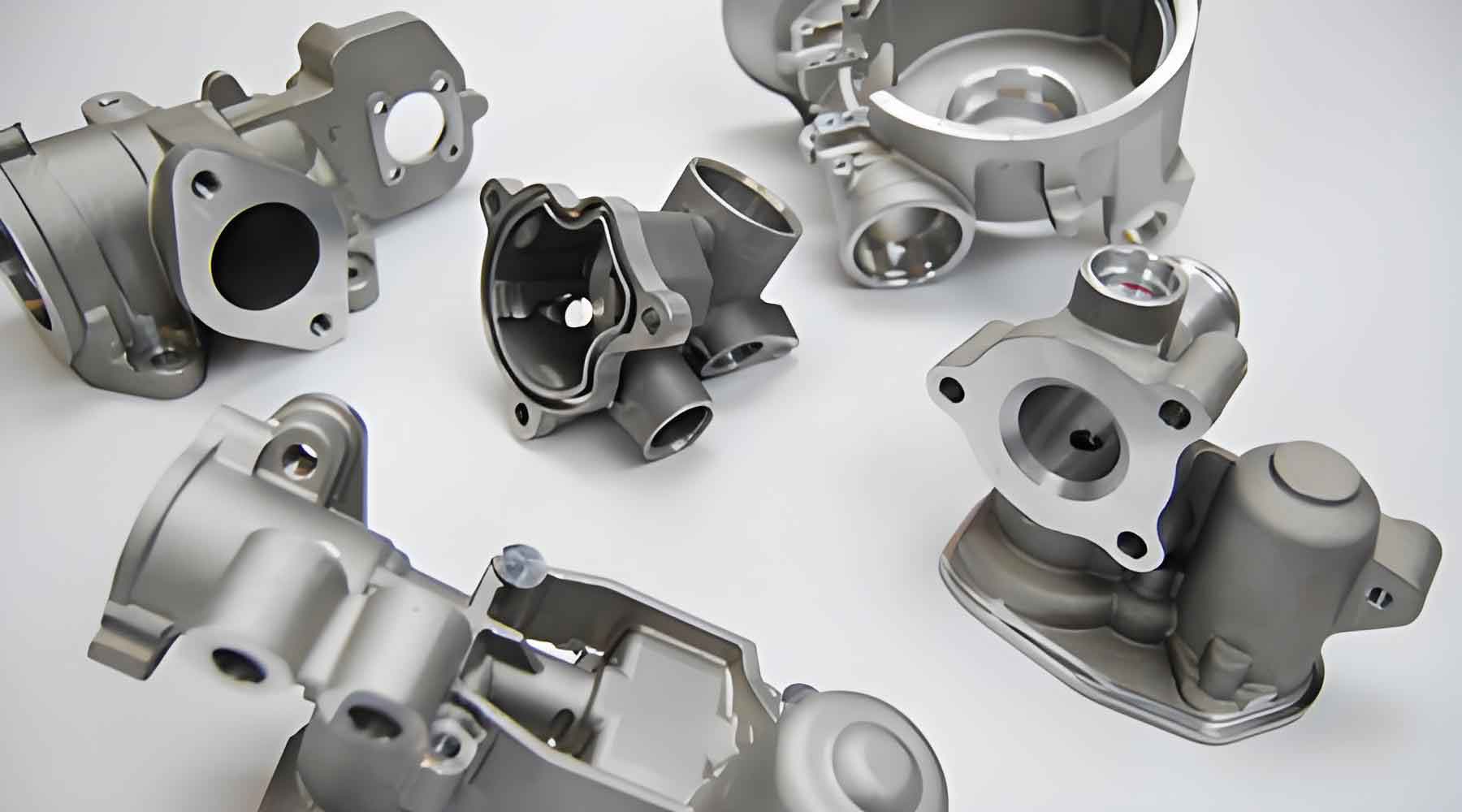
In the production of critical components for advanced aerospace engines and gas turbines, the lost wax investment casting process is widely employed due to its ability to achieve complex geometries and high-dimensional accuracy. As a key hot-end part in main combustion chambers, vortex castings made from K605 alloy must withstand extreme operational environments, including high temperatures and corrosive conditions. However, during the lost wax investment casting of these components, surface defects such as pitting and凹坑 often arise, compromising the integrity and performance of the castings. This study investigates the root causes of these defects and proposes effective countermeasures to enhance surface quality and production efficiency.
The lost wax investment casting method involves creating a ceramic shell around a wax pattern, which is subsequently melted out to form a mold cavity. The K605 alloy melt is then poured into this cavity at temperatures exceeding 1450°C, leading to intimate contact between the molten metal and the refractory material. This interaction can result in mechanical or chemical sand adhesion, where complex physico-chemical reactions occur at the interface. In severe cases, these reactions alter the surface composition of the casting, leading to defects like pitting and凹坑. Initial observations revealed localized black spots on the shell surface, which were correlated with the casting defects, though the exact mechanism required further exploration.
To address these issues, we conducted a comprehensive analysis using various materials and methods. The K605 alloy, with its specific chemical composition, was cast using the lost wax investment casting technique. The shell-making process initially employed zircon flour for the primary layer, but this led to surface imperfections. We switched to fused alumina for the face coat to mitigate interfacial reactions. The chemical composition of the K605 alloy is detailed in Table 1, which highlights elements like Cr, Ni, and Co that influence the casting behavior.
| Element | C | O | Al | Si | Cr | Fe | Mn | Ni | W | Co |
|---|---|---|---|---|---|---|---|---|---|---|
| K605 | ≤0.40 | – | – | ≤0.40 | 19.00-21.00 | ≤3.00 | 1.00-2.00 | 9.00-11.00 | 14.00-16.00 | Balance |
Our experimental approach involved preparing shells with different face coat materials and analyzing the defects using stereomicroscopy, scanning electron microscopy (SEM), and energy-dispersive X-ray spectroscopy (EDS). For instance, the ZSA302 stereomicroscope was used to examine the morphology of surface defects, while the FEI QVANT600 SEM facilitated detailed microstructural analysis. EDS was performed on the Link ISIS 6498 system to identify elemental variations in defect regions. The shell-making parameters were systematically varied, as summarized in Table 2, to optimize the process and reduce defects in the lost wax investment casting.
| Layer | Binder | Refractory Material | Viscosity (s) | Stucco Material | Grain Size (mesh) | Drying Time (h) |
|---|---|---|---|---|---|---|
| Face Coat | Silica Sol + Fused Alumina Powder | Fused Alumina | 45-51 | Fused Alumina Sand | 80 | 3-4 |
| Transition Layer | Silica Sol + Mullite Powder | Mullite | 22-36 | Mullite Sand | 30-60 | ≥6 |
| Reinforcement Layer | Silica Sol + Mullite Powder | Mullite | 8-12 | Mullite Sand | 16-30 | ≥8 |
| Sealing Layer | Silica Sol + Mullite Powder | Mullite | 8-12 | – | – | ≥12 |
The initial use of zircon flour in the face coat resulted in black spots on the shell surface, which corresponded to pitting and凹坑 on the castings. SEM images showed a honeycomb-like structure in these black spots, with cracks and localized spalling. EDS analysis detected elements such as Al, O, Si, and Cr in the defect areas, indicating interfacial reactions. For example, the reaction between Cr oxides from the alloy and FeO from the shell can be described by the equation: $$ \text{Cr}_2\text{O}_3 + 3\text{FeO} \rightarrow 2\text{Cr} + 3\text{FeO} \cdot \text{SiO}_2 $$ This reaction contributes to the formation of low-melting-point compounds like fayalite (2FeO·SiO2), which melts at around 1178°C and penetrates the shell through microcracks, exacerbating defects in the lost wax investment casting process.
Further investigation revealed that the back-layer sand contained elevated iron levels, with Fe2O3 content reaching up to 25.7% in some “black sand” particles. During shell firing at temperatures between 1250°C and 1400°C, these iron-rich compounds melted and migrated to the surface, forming black spots. The overall reaction can be modeled using thermodynamic principles, where the Gibbs free energy change ΔG for the formation of silicates is negative under these conditions, favoring the reaction: $$ \Delta G = \Delta H – T\Delta S $$ Here, ΔH is the enthalpy change, T is the temperature, and ΔS is the entropy change. This equation helps explain why iron silicates form readily during the lost wax investment casting shell preparation.
To mitigate these defects, we implemented several improvements in the lost wax investment casting process. First, we adopted an integrated mold design for wax pattern production, which eliminated parting lines and reduced post-casting finishing work. This approach enhanced the consistency and surface quality of the wax patterns, directly impacting the final casting quality. Second, we modified the gating system from a side-gating to a top-gating scheme, which improved wax removal and prevented residual spots on the shell surface. This change addressed issues like incomplete dewaxing, which previously led to localized defects.
In terms of shell-making, we replaced zircon flour with fused alumina powder for the face coat, as alumina offers better chemical inertness against K605 alloy reactions. The viscosity of the face coat slurry was controlled between 45 and 51 seconds, and the coating thickness was maintained at 0.09-0.10 mm to ensure denseness and prevent penetration by back-layer stucco. Additionally, we enforced strict controls on the iron content in back-layer sands, requiring Fe2O3 levels below 0.5% to minimize the formation of low-melting-point compounds. These adjustments in the lost wax investment casting process significantly reduced the defect rate from 85% to under 5%.
The effectiveness of these measures was evaluated through multiple casting trials. For instance, the integrated mold design reduced pattern-making time by 30%, while the top-gating system improved yield by 15%. The use of fused alumina in the face coat enhanced shell stability, as described by the formula for coating integrity: $$ I_c = \frac{\sigma_t \cdot d}{\mu} $$ where I_c is the integrity index, σ_t is the tensile strength, d is the coating thickness, and μ is the dynamic viscosity. Higher I_c values correlate with better defect resistance in lost wax investment casting.
In conclusion, the surface pitting and凹坑 defects in K605 alloy vortex castings produced by lost wax investment casting are primarily caused by interfacial reactions between alloy elements like Cr and iron oxides in the shell. The migration of molten iron silicates through shell imperfections leads to black spots and subsequent casting defects. By adopting an integrated mold, optimizing the gating design, using fused alumina for the face coat, and controlling back-layer sand iron content, we achieved substantial improvements in surface quality and production efficiency. This study underscores the importance of material selection and process control in the lost wax investment casting method for high-performance alloys.
Future work could focus on developing advanced refractory materials with even lower reactivity and exploring real-time monitoring techniques during shell firing to further enhance the lost wax investment casting process. Overall, these findings provide a robust framework for addressing surface defects in complex castings, ensuring reliability in demanding applications like aerospace engines and gas turbines.