
Abstract
This article delves into the structure and technical specifications of ductile iron tray castings, focusing on the issues of porosity and shrinkage defects encountered during production. Through comprehensive analysis, the root causes of these defects are identified, and corresponding countermeasures are proposed. The implementation of these measures has proven effective in eliminating porosity and shrinkage defects in the same type of tray castings, ensuring the stable production of high-quality large-scale ductile iron tray castings.
1. Introduction
Tray castings, as an integral part of coal pulverizers, play a crucial role in rotating and grinding coal blocks into coal powder, thereby enhancing coal combustion efficiency. Given their exposure to high torsion and impact vibration loads, tray castings demand high strength, toughness, and plasticity, making QT400-15 material the preferred choice. However, the unique structural features of tray castings, such as uneven wall thickness and inadequate ventilation, often lead to defects like porosity and shrinkage, which can severely impact their quality and even result in scrap.
2. Structure and Technical Requirements of Ductile Iron Tray Castings
2.1 Structure Description
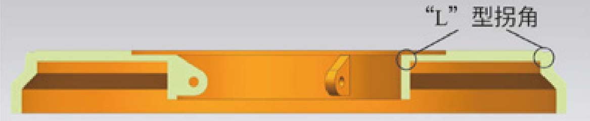
Tray castings are large-scale disc-shaped castings with outer diameters ranging from 3,090 mm to 5,000 mm, a height of 370 mm, and gross weights between 5.1 and 9 tons. The minimum wall thickness is 55 mm, while the peripheral wall thickness is 80 to 100 mm. Notably, the castings feature abrupt “L”-shaped corners that serve as hot spots, prone to defects.
2.2 Technical Specifications
The tensile strength of single-cast test specimens should be no less than 400 MPa, with an elongation after fracture of at least 15%. For attached test specimens, the tensile strength should be no less than 370 MPa, with an elongation after fracture of at least 11%.
3. Casting Process and Defects
3.1 Casting Process
The casting process utilizes furan resin-bonded sand molding, with the largest diameter surface serving as the parting surface. The outer contour is formed by the sand box, while the inner contour is shaped by sand cores. These sand cores consist of a ring-shaped core and a cylindrical core. A bottom-pouring gating system ensures adequate pouring speed and slag retention. To leverage the graphitization expansion of ductile iron, risers with a lower cross-section of 20 mm × 50 mm and an upper cross-section of 80 mm × 150 mm are placed at thick sections. Additionally, dark chills are positioned around the ring core to aid in cooling and ensure casting density.
3.2 Defects Overview
The tray castings produced using the aforementioned process exhibit porosity on the outer circumferential surface and shrinkage defects within the inner circle after processing.
4. Cause Analysis of Defects
4.1 Porosity
Porosity can be classified into exudative porosity, reactive porosity, and invasive porosity. The porosity observed on the tray castings is invasive, characterized by smooth pore walls distributed on the casting surface. This type of porosity occurs when a large amount of gas is generated in the sand mold and sand core under the action of high-temperature molten metal. When the gas pressure at the metal-mold interface increases and exceeds the external resistance, gas infiltrates the liquid metal, forming bubbles on the mold wall. These bubbles, if not escaping in time, solidify into invasive porosity.
Sampling revealed that the moisture content of the sand core and sand mold was between 0.5% and 0.6%, exceeding the required limit of ≤0.3%. Thus, excessive moisture in the mold is identified as the cause of invasive porosity on the tray surface.
4.2 Shrinkage
Shrinkage is essentially a manifestation of shrinkage cavities. Ductile iron, with a wide crystallization temperature range, is prone to dispersed shrinkage defects due to the sum of liquid and solidification shrinkage exceeding solid-state shrinkage. Shrinkage defects commonly occur in the center of casting walls, hot spots, riser roots, and near ingates. Based on the tray’s cross-sectional view, it is evident that defects arise in the thick, hot-spot areas, confirming them as shrinkage defects.
5. Countermeasures
5.1 Addressing Porosity
The primary causes of porosity are excessive mold moisture and poor ventilation. Therefore, countermeasures focus on reducing mold moisture and improving mold ventilation.
Table 1: Comparison of Moisture Content and Defect Occurrence
| Measure | Moisture Content (%) | Defect Occurrence |
|---|---|---|
| Before | 0.5 – 0.6 | High |
| After | ≤ 0.3 | Low |
- Reducing Mold Moisture: Since the sand core’s size prevents it from entering the drying kiln, in-cavity baking of the sand core is employed to reduce its moisture content. By controlling the moisture content of the molding sand below 0.3%, the probability of porosity significantly decreases.
- Improving Mold Ventilation: Incorporating vent ropes in the sand core and sand mold enhances air outlet and ventilation, mitigating the risk of invasive porosity.
5.2 Addressing Shrinkage
To address shrinkage defects, strategies aim to convert dispersed shrinkage into concentrated shrinkage cavities and transfer these to the risers, ensuring qualified castings. Additionally, leveraging graphitization expansion is employed to prevent shrinkage defects. The optimized process includes:
- Modifying Chill Placement and Type: Shifting from dark chills to bright chills, enhances the chilling effect, eliminates hot spots at the “L”-shaped corners, and promotes balanced solidification.
- Enlarging Risers: Increasing the size of the risers from 20×50/80×150 to 20×100/170×195 enhances liquid feeding, preventing shrinkage defects. Furthermore, timely sealing of the riser neck channel during the later stages of solidification leverages the casting’s own graphitization expansion to reduce shrinkage.
- Adjusting Carbon Content: Without causing graphite floatation or blooming, the carbon content is increased to approximately 3.75%, combined with a carbon equivalent of 4.3% to 4.5%, reaching near-eutectic or hypereutectic points. This ensures more and more sufficient graphite precipitation, facilitating the “self-feeding” effect.
6. Conclusion
The implementation of the aforementioned measures has resulted in the production of tray castings free from porosity and shrinkage defects. The tensile strength of the 70 mm attached test specimens ranges from 409 to 464 MPa, with an elongation after fracture between 13% and 17%. The nodularity is grade 2, and the graphite particle size is grade 7, consistently meeting national standards.
By reducing mold moisture through baking sand cores and molds, improving mold ventilation, optimizing chill placement and type to eliminate hot spots, enhancing riser size for improved liquid feeding, and increasing molten iron carbon content for enhanced self-feeding ability, we have effectively mitigated porosity and shrinkage defects in ductile iron tray castings. These measures have facilitated the stable production of qualified large-scale QT400-15 disc-shaped ductile iron castings.