
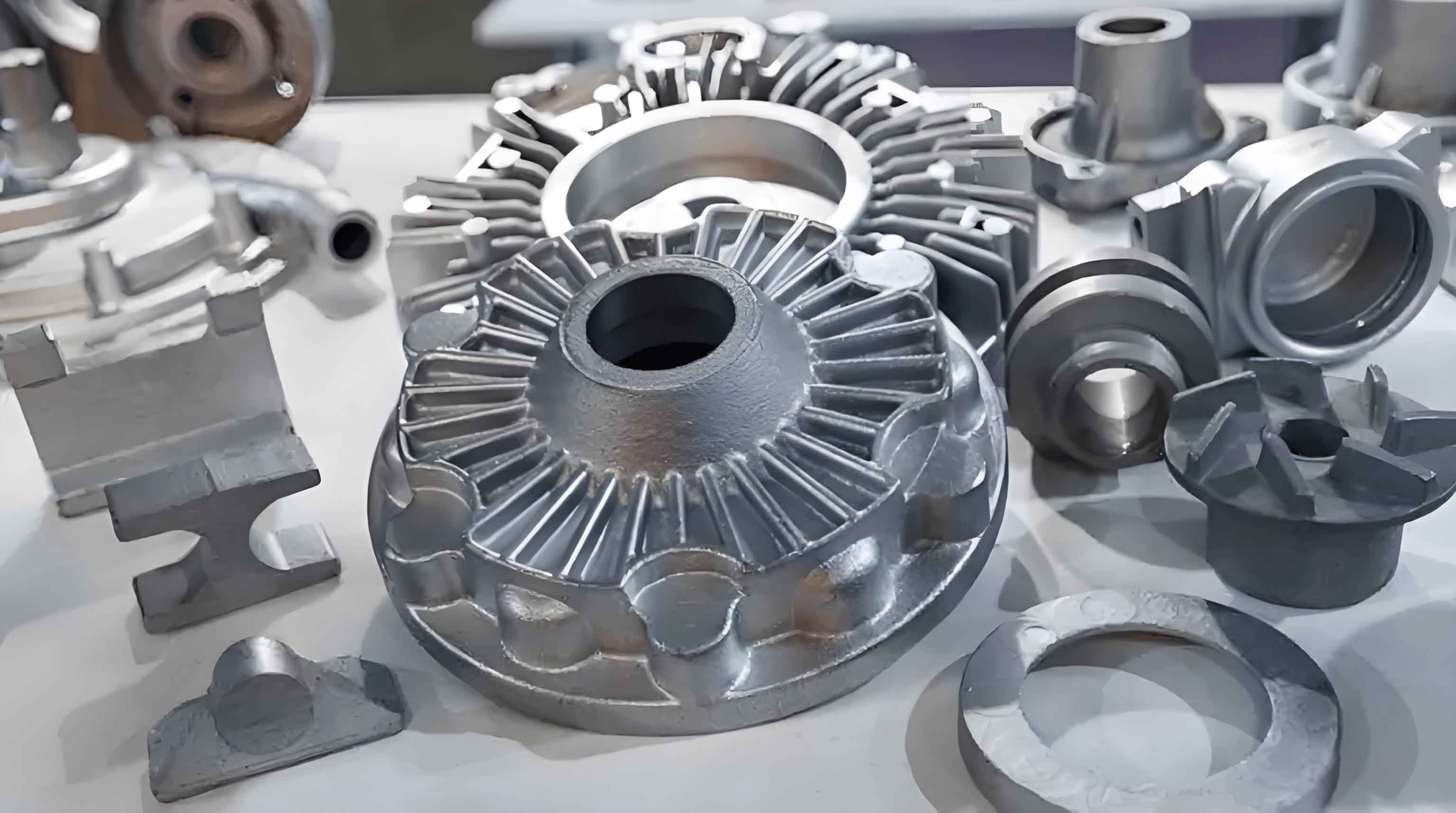
The cylinder head is one of the main components of a diesel engine. During the working process of a diesel engine, the maximum temperature in the combustion chamber can reach about 2,000 K (approximately 1,700 °C). The cylinder head not only withstands the high-temperature cyclic thermal shock load brought by the combustion chamber, but also bears the impact load of the high-pressure cycle in the combustion chamber. Especially for the high-pressure side and the inside of the valve seat hole, no casting defects are allowed. The oil pipe holes and fuel injection holes on the cylinder head have a relatively harsh working environment, and the internal structure is required to be dense. Therefore, the internal and external quality requirements for the cylinder head casting itself are relatively high. The structure of the casting is shown in Figure 1.
The material of the 16V190 cylinder head casting is RuT300, which has excellent mechanical properties, thermal fatigue resistance, and good air tightness. In order not to affect the water flow cooling effect in the water cavity of the cylinder head, the inside of the water cavity is required to be smooth without burrs, and the wall thickness between the water cavity and the air passage must be controlled within 6 to 8 mm. The overall dimensional accuracy of the casting is controlled at the CT10 to CT11 level .
The overall casting mold of the cylinder head is selected as resin sand machine molding, with a design of 2 pieces per mold. Some sand cores are made by hand with resin sand, while the water cavity core and bolt hole core are made by hot core box 覆膜 sand core making. Due to the relatively complex inner cavity surface of the cylinder head casting and the relatively complex structure, a total of 22 sand cores are designed in the process. The mold is coated with water-based coating by spraying, and dried in a drying oven. The drying and heat preservation temperature is 170 °C ± 10 °C, and the heat preservation time is 3.5 to 4 hours. The sand core is coated with a composite process of alcohol-based quartz coating and water-based graphite coating. In the process of mold assembly, the sand cores are assembled by a layered superposition method, and a lot of foundry adhesive is applied to the mating surface of the sand cores. After the mold assembly is completed, it is dried in a drying oven. The weight of the cylinder head casting is 89 kg per piece, and the local wall thickness of the casting is only 6 mm. Technically, it is required that the molten iron filling and shaping should be rapid and stable, so a stepped gating system is adopted, with a pouring temperature of 1,380 to 1,390 °C and a pouring time controlled within 15 to 20 seconds.
- Analysis of Casting Defect Causes
During the casting production process of the 16V190 cylinder head, typical defects such as sand holes, underfilling, inner cavity burrs, and pores are prone to occur. The formation causes of these casting defects are specifically described below.
1.1 Sand Holes
The sand hole defect of the 16V190 cylinder head casting refers to the presence of redundant holes on the inside or surface of the casting after cleaning. In most cases, the main cause of sand holes in the casting is improper operation during the mold assembly and box closing process. Insufficient installation of the bolt hole core, non-perpendicularity between the bolt hole core and the bottom surface of the core insertion, and unstable lifting of the upper mold by the crane during box closing will all lead to the breaking of the bolt hole core by the upper mold during the box closing operation, causing the sand core to break and fall into the mold cavity, which is not easy to check, resulting in sand holes in the casting after later pouring (Figure 2). In addition, the upper water cavity and the fuel injector hole core use split sand cores, which are integrally inserted after being bonded by foundry adhesive, and there will inevitably be some cumulative errors in the core bonding. At this time, if there is floating sand or coating accumulation in the fuel injector hole core seat, resulting in improper core insertion, and the stability of the upper mold lifting during the box closing process is not well controlled, it will also break or crush the sand core during the box closing process, resulting in sand dropping phenomenon, which also causes local sand hole defects in the casting after pouring .
1.2 Inner Cavity Burrs
The inner cavity burr defect of the 16V190 cylinder head casting refers to the presence of an irregular and uneven layer similar to a “thin iron sheet” in the gas path, water path, or other parts. There are mainly two possible reasons for the formation of inner cavity burrs:
(1) Due to the relatively complex structure of the water cavity of the cylinder head, the structural sand core in the water cavity is made by the hot core box core shooting process, but the coated sand is prone to form a settlement problem due to heat softening [2], resulting in a relatively thin core shell layer. During the natural cooling process of the sand core, it will contract and generate capillary cracks, and after the molten iron is poured into the process, the sand core will crack under the high-temperature thermal radiation of the molten iron, thereby allowing the molten iron to infiltrate the sand core and form burrs of different degrees.
(2) Due to the relatively complex structure of the water cavity of the cylinder head, the local wall thickness of the inner cavity is only 6 mm, and the intake core and the exhaust core need to be interspersed with the water cavity core, which leads to the design of the water cavity core into two sand cores in the process design (Figures 4 and 5). Later, the two sand cores are bonded with foundry adhesive according to the actual situation, which will make the mating surface of the two sand cores not fit tightly enough, increasing the possibility of molten iron infiltration and resulting in an increased probability of inner cavity burrs.
1.3 Underfilling
The main cause of the underfilling defect of the 16V190 cylinder head casting is the phenomenon of molten iron overflow at the parting surface during the pouring process, that is, the leakage of the box [3]. It is also affected by factors such as the purity of the molten iron, the height of the pouring temperature, the correct placement of the filter, and the leakage of the molten iron caused by the air holes, as shown in Figure 6.
1.4 Pores
The main cause of the pore defect of the 16V190 cylinder head casting is the use of resin self-hardening sand for mold making and core making. The resin and curing agent in the molding sand will generate a large amount of gas under the thermal effect of the high-temperature molten iron during the pouring process, and be entrained into the mold during the pouring process. Eventually, the gas inside the mold cannot be smoothly discharged, resulting in pores in the casting after cooling and shaping, and most of the pores are invasive pores .
- Improvement Measures and Effects
2.1 Improvement Measures for Sand Hole Defects
(1) Make core insertion cards in combination with the actual situation to ensure that the sand core can be inserted in place. The actual cylinder head uses a core assembly casting process. Make core insertion cards according to the actual core insertion, especially for the mating surface involving the height direction of the sand core, a height confirmation card must be made to reduce the cumulative error of core insertion, so as to prevent the upper mold from crushing the bolt hole core and related sand cores during the box closing process and avoid the fracture of the sand core during the core insertion process.
(2) Make inner cavity wall thickness calipers and 6 mm soft leather lines in combination with the casting structure. Use the wall thickness calipers to check the regular wall thickness size, and use the soft leather lines as inspection feeler gauges for the irregular curved wall thickness of the air passage and other parts to pass through the curved cavity to ensure the minimum wall thickness size of the curved parts, thereby ensuring that the relevant sand cores in the inner cavity are inserted in place and preventing the sand cores from being crushed during the box closing process.
(3) Regularly carry out quality awareness training to enhance the quality awareness of the operators. During the core insertion process, clean up the floating sand or accumulated coating in the core seat one by one, and check and verify the perpendicularity of the bolt hole core one by one after core insertion. During the box closing process, a special person is assigned to check whether there is a collision between the bolt hole core and the upper core seat to ensure a smooth box closing and prevent the phenomenon of crushing the bolt hole core and other sand cores by the upper mold.
2.2 Improvement Measures for Inner Cavity Burr Defects
(1) In order to prevent the generation of inner cavity burrs in the casting, efforts should be made to improve the quality of the water cavity core sand core itself, control process parameters such as core shooting temperature and holding time, and ensure that the thickness of the core shell layer is > 5 mm. In addition, use alcohol-based zircon powder coating for two times of dipping before mold assembly to improve the density, refractoriness, and strength of the surface of the sand core [2].
(2) Strengthen the quality control of the details of the water cavity core insertion to ensure that the water cavity core is inserted in place. When inserting the core, first conduct a trial fit of the upper and lower water cavity sand cores, check the mating situation of the mating surface, and appropriately modify the mating surface of the two sand cores according to the shape of each part to make the mating smooth, and control the mating surface gap to the minimum. Secondly, when inserting the upper water cavity core, first evenly apply a layer of foundry adhesive on the mating surface of the lower water cavity core to avoid the exhaust slot, then close the upper water cavity core, apply a little pressure to make the foundry adhesive extrude to both sides, take out the upper core and check the bonding situation of the two sand cores, scrape off the excess foundry adhesive, and finally, use foundry adhesive for appropriate repair of the not tightly bonded areas, and then close the upper sand core and apply pressure again to ensure that the mating surface of the two sand cores is tight enough, reduce the possibility of molten iron infiltration into the sand core, and reduce the burrs in the water cavity.
2.3 Improvement Measures for Underfilling Defects
(1) Prevent the leakage of the box during the pouring process. First, check the status of the sand box and other tooling during the molding process, and do not use the sand box with missing or loose parts to prevent the overall sinking of the mold. Secondly, before box closing, place a φ4 mm sealing mud strip along the circumference of the parting surface of the lower mold to avoid the runner. When fastening the mold with the box clamp, it needs to be fastened diagonally at the same time to ensure the uniform force of the mold.
(2) Control the quality of the molten iron and the quality of the pouring process. On the one hand, during the pouring process, it is necessary to control the quality of the original molten iron, do a good job of slag removal and other work. On the other hand, it is necessary to strengthen the slag-blocking operation during the pouring process. When pouring, the pouring ladle nozzle must be close to the pouring cup, quickly fill the pouring cup, and maintain the liquid level in the pouring cup to avoid the generation of turbulence, vortex, or even splashing during the filling process, and put an end to the blockage of the filter hole caused by the molten slag during the pouring process.
(3) Ensure the correct placement of the ceramic filter. In the process design, a ceramic filter is placed at the lap joint of the sprue and the runner in the gating system to play the role of slag blocking [3]. When placing the ceramic filter, it is necessary to ensure that the inlet hole is facing the pouring cup to ensure that the molten iron flows through the filter hole in the forward direction and flows into the mold.
(4) Control the unobstructed air holes, air vents, etc., and handle them properly in the later stage. Ensure that the air passages in the sand mold and the sand core are unobstructed and do a good job in making the air vents of the sand core in the mold assembly process. The air vents should be reserved in the upper mold as much as possible. In addition, necessary sealing should be done around the air vents to prevent the molten iron from entering the air vents and causing iron leakage.
(5) Control the pouring temperature. During the pouring process of the cylinder head, the initial pouring temperature is controlled according to the upper limit of the process (1,390 °C), and proper insulation measures are taken for the molten iron in the ladle, and appropriate insulation materials are covered. During the pouring process, it should be poured smoothly, orderly, and quickly, and try to ensure that the pouring temperature in the later stage of the pouring is within the range of the process requirements.
2.4 Improvement Measures for Pore Defects
(1) Improve the process and rationally design the gating system. When designing the process, it is necessary to ensure that the design of the inner runner is in line with the principle of smooth molten iron filling and smooth gas floating, and the design of the riser, air vents, etc. should have correct positions and reasonable quantities, which is conducive to the smooth discharge of the gas in the mold cavity.
(2) Control the exhaust effect of the sand core. Before the sand core is dipped, block the air passage holes to prevent the coating from blocking the air passage during the dipping process. In addition, open up all the air passage holes in the core head of the sand core and the blocked air passage holes before dipping, and extend them to the thick part of the sand core, and pour out part of the crushed sand in the sand core to make the air passage of the sand core unobstructed.
(3) Do a good job in the ventilation of the sand core and the mold. Before core insertion, according to the position of the core head in the mold cavity, open the ventilation holes from the outside of the mold to the core seat, apply foundry adhesive in the core seat to block the gap of the core head, apply foundry adhesive around the ventilation holes to prevent the molten iron from entering the ventilation passage and blocking the air passage during the pouring process, so that the gas generated in the sand core can be smoothly discharged from the mold.
In summary, by taking corresponding improvement measures, the occurrence of sand holes, inner cavity burrs, underfilling, pores, and other defects of the 16V190 cylinder head casting has been effectively avoided in the actual production process, and the reject rate of the cylinder head casting has decreased from the original 3.8% to 0.8%, achieving good implementation results.
- Conclusion
In view of the typical casting defect problems such as sand holes, inner cavity burrs, underfilling, and pores existing in the cylinder head, analyze the causes of related problems according to the actual situation, and take corresponding solutions to effectively improve the product quality of the cylinder head casting, and the reject rate of the cylinder head casting has decreased by 3%. In view of the fact that the control of the details quality in the cylinder head casting production process has a direct impact on the quality of the cylinder head casting, combined with production experience and practice, rationally design and improve the corresponding casting process, standardize the on-site operation requirements, formulate relevant measures and implement them in place, which greatly reduces the amount of casting scrap, improves production efficiency, and reduces production costs.
To sum up, this article details the casting process and defect analysis of the 16V190 cylinder head, as well as the corresponding improvement measures and their effects. By understanding and implementing these measures, the quality of the cylinder head castings can be effectively improved, and the reject rate can be significantly reduced. At the same time, it emphasizes the importance of detail control in the casting production process, which is crucial for ensuring the quality of the castings. Reasonable design and improvement of the casting process, as well as standardized on-site operation requirements, can help enterprises reduce scrap, improve production efficiency, and lower production costs.
In addition, the following is a summary of the defect causes and improvement measures in tabular form for easier reference:
| Defect | Causes | Improvement Measures |
|---|---|---|
| Sand Holes | – Insufficient installation of bolt hole core, non-perpendicularity between bolt hole core and bottom surface of core insertion, unstable lifting of upper mold during box closing. – Cumulative errors in core bonding, floating sand or coating accumulation in fuel injector hole core seat, and poor stability control during box closing. | – Make core insertion cards, especially for mating surfaces involving the height direction of the sand core. – Make inner cavity wall thickness calipers and 6 mm soft leather lines. – Regularly carry out quality awareness training, clean up floating sand or accumulated coating in the core seat, check the perpendicularity of the bolt hole core, and have a special person check for collision during box closing. |
| Inner Cavity Burrs | – Heat softening of coated sand in the hot core box core shooting process leads to a thin core shell layer, which cracks during natural cooling and allows molten iron to infiltrate. – The complex water cavity structure requires splitting the water cavity core into two, and the mating surface is not tight enough, increasing the possibility of molten iron infiltration. | – Improve the quality of the water cavity core sand core itself by controlling process parameters such as core shooting temperature and holding time, and use alcohol-based zircon powder coating for two times of dipping |