
The persistent challenge of defect formation in cast components represents a significant barrier to manufacturing efficiency and product reliability. In my extensive experience with lightweight alloy casting, few defects are as prevalent and detrimental as slag inclusions. This article presents a comprehensive, first-person analysis of a specific case involving slag inclusions in sand-cast magnesium alloy crankcases, detailing the investigative methodology, root cause analysis, and the systematic engineering solutions implemented to resolve the issue. The focus will remain squarely on understanding and combating slag inclusions, a defect that manifests as non-metallic compounds trapped within the casting matrix, severely compromising mechanical integrity.
The initial scenario involved the production of AZ91D magnesium alloy crankcase壳体 castings with a consistent and unacceptable scrap rate. Statistical process control data revealed that approximately 30% of the produced castings, specifically 37 out of 125 units, were rejected due to the presence of internal defects identified as slag inclusions. This level of waste was economically unsustainable and demanded immediate technical intervention. The castings were substantial, weighing approximately 6.1 kg with overall dimensions of 330 mm x 200 mm x 250 mm. The original foundry practice employed a top-gating system with an open ratio (sprue area : total runner area : total ingate area) of 1 : 2 : 4. The pouring temperature was maintained at 720°C with a fill time between 12 to 14 seconds.
Non-destructive evaluation, primarily through radiographic inspection, provided the first clues. The slag inclusions appeared on X-ray film as irregular, dark patches with relatively sharp but non-geometric contours. Their photographic density varied, and they often presented as blocky or, more characteristically, in continuous flake-like formations. This morphology is a classic signature of oxide-based slag inclusions. Visually and upon machining, these defects presented as rough, irregular cavities, sometimes with yellowish-brown streaks on the surface. Fractures through these areas often revealed a layered structure with dark grey or blackish surfaces, clearly indicating the presence of non-metallic films.
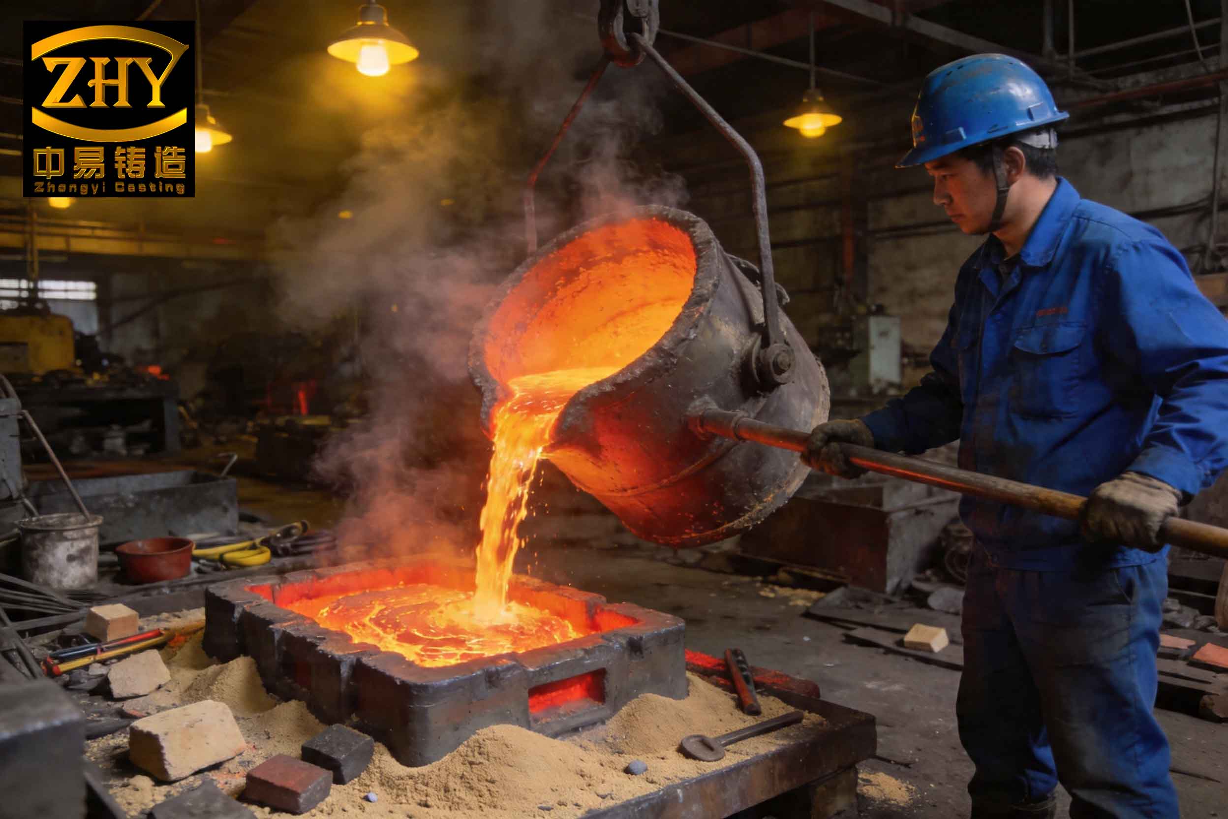
To understand why magnesium alloys are particularly susceptible to slag inclusions, one must first consider their inherent physicochemical properties. Magnesium alloys offer an exceptional strength-to-weight ratio, but their high chemical reactivity is a double-edged sword. The propensity for oxidation is dramatically higher than for aluminum or iron alloys. During melting and pouring, molten magnesium readily reacts with oxygen in the air to form magnesium oxide (MgO). More critically, it can react with moisture present in the air, binders, or even the sand mold itself, according to the violent reaction: $$\text{Mg}_(l) + \text{H}_2\text{O}_(v) \rightarrow \text{MgO}_(s) + \text{H}_2\uparrow$$ This reaction not only generates oxide dross but also releases hydrogen gas, which can lead to gas porosity if not properly managed. Furthermore, at elevated temperatures, magnesium can reduce silica (SiO$_2$) in the molding sand: $$2\text{Mg}_(l) + \text{SiO}_2_(s) \rightarrow 2\text{MgO}_(s) + \text{Si}_(in melt)$$ $$4\text{Mg}_(l) + \text{SiO}_2_(s) \rightarrow 2\text{MgO}_(s) + \text{Mg}_2\text{Si}_(s)$$ These reaction products contribute directly to the population of non-metallic inclusions, or slag inclusions, within the melt.
The formation of slag inclusions can be systematically categorized into two primary origins: primary and secondary formations. My investigation had to discern which was the dominant contributor.
- Primary Slag Inclusions: These are generated during the melting and holding stages. Causes include contaminated charge materials (dirty ingots, scrap returns with oxide skins), inadequate or low-quality flux cover during melting, and insufficient or improper melt refining (e.g., poor slag removal after flux treatment). These oxides, chlorides, or other compounds exist in the melt prior to pouring.
- Secondary Slag Inclusions: These form during the transfer and mold-filling process. Turbulent flow during pouring entraps air, causing immediate oxidation of the metal stream. A poorly designed gating system that creates splashing, vortexing, or excessive velocity promotes this turbulence. The reaction with the mold atmosphere and sand, as described by the equations above, also occurs during filling, generating new oxides in situ within the mold cavity.
Given the observed flake-like, continuous nature of the slag inclusions in the radiographs—often aligned with the flow path—the evidence strongly pointed towards secondary slag inclusions as the root cause. The original top-gating system was a prime suspect. While excellent for thermal gradient control and feeding, a top-gate results in a high, uncontrolled drop of metal into the mold cavity. This fall creates massive turbulence, splashing, and extensive surface area exposure of the molten metal to the mold atmosphere, creating a perfect environment for the generation of secondary slag inclusions.
The logical and most impactful corrective action was a complete redesign of the gating system. The goal was to achieve quiescent, laminar fill to minimize oxide generation. This mandated a shift from a top-pour to a bottom-pour, or naturally pressurized, system. The principle is to use the gating channels themselves to absorb the initial kinetic energy of the stream and deliver metal into the mold cavity at a low, controlled velocity from the bottom up. To achieve this scientifically, I based the new design on the theory of large orifice outflow, which provides more accurate modeling of interconnected flow in gating systems compared to traditional hydraulic formulas.
Step-by-Step Gating System Redesign
1. Determination of Pouring Time (τ): The required fill time is governed by the need to maintain a minimum upward velocity of the metal front to avoid mist runs and cold shuts, while also being fast enough to prevent premature freezing. For a casting of this wall thickness and height (h$_c$ = 25 cm), the recommended average upward velocity (v$_l$) is between 2.0 and 3.0 cm/s. Selecting a conservative v$_l$ = 2.5 cm/s gives:
$$ \tau = \frac{h_c}{v_l} = \frac{25\ \text{cm}}{2.5\ \text{cm/s}} = 10\ \text{s} $$
This was a reduction from the original 12-14s, aiming for a slightly faster but controlled fill.
2. Selection of Gating Ratio: For a bottom-gate system designed for slag inclusion control, a choke at the sprue is effective. I maintained an open system but adjusted the ratios slightly to ensure progressive filling: F$_{sprue}$ : ∑F$_{runner}$ : ∑F$_{ingate}$ = 1 : 2 : 4. This ratio helps maintain a full sprue and minimizes aspiration.
3. Calculation of Effective Area Ratios (k$_1$, k$_2$): These ratios are crucial for applying the large orifice outflow model, as they account for the interdependent flow restriction of each gating section.
$$ k_1 = \frac{F_{sprue}}{\sum F_{runner}} = \frac{1}{2} = 0.5 $$
$$ k_2 = \frac{F_{sprue}}{\sum F_{ingate}} = \frac{1}{4} = 0.25 $$
4. Calculation of Mean Effective Pressure Head (h$_p$): In a bottom-gated system, the static pressure head decreases as the mold fills. The mean effective head is not simply the sprue height. The formula incorporating the area ratios is:
$$ h_p = \frac{k_2^2}{1 + k_1^2 + k_2^2} \left( H – \frac{h_c}{2} \right) $$
Where H is the total height of the sprue (40 cm) and h$_c$ is the casting height (25 cm).
$$ h_p = \frac{0.25^2}{1 + 0.5^2 + 0.25^2} \left( 40 – \frac{25}{2} \right) = \frac{0.0625}{1 + 0.25 + 0.0625} (40 – 12.5) $$
$$ h_p = \frac{0.0625}{1.3125} \times 27.5 \approx 1.31\ \text{cm} $$
This surprisingly low value of h$_p$ reflects the significant flow resistance of the interconnected, open gating system when analyzed as a whole, validating the need for this sophisticated calculation approach.
5. Calculation of Total Ingate Area (∑F$_{ingate}$): Using the basic flow equation, modified with the calculated h$_p$:
$$ \sum F_{ingate} = \frac{C}{\rho \mu \tau \sqrt{2 g h_p}} $$
Where:
- C = Casting mass = 6.1 kg
- ρ = Density of molten AZ91D ≈ 0.0018 kg/cm³
- μ = Flow loss coefficient (accounts for friction, bends, etc.). For a well-designed sand system, μ ≈ 0.35.
- τ = Pouring time = 10 s
- g = Gravitational acceleration = 980 cm/s²
- h$_p$ = 1.31 cm
$$ \sum F_{ingate} = \frac{6.1}{0.0018 \times 0.35 \times 10 \times \sqrt{2 \times 980 \times 1.31}} $$
First, calculate the radical: $\sqrt{2 \times 980 \times 1.31} = \sqrt{2567.6} \approx 50.67\ \text{cm/s}$.
Then the denominator: $0.0018 \times 0.35 \times 10 \times 50.67 \approx 0.0018 \times 177.345 \approx 0.3192$.
Finally: $\sum F_{ingate} \approx \frac{6.1}{0.3192} \approx 19.1\ \text{cm}^2$.
I rounded this up to a standardizable 20 cm² for practical pattern-making.
6. Determination of Sprue and Runner Areas:
$$ F_{sprue} = \frac{\sum F_{ingate}}{4} = \frac{20}{4} = 5\ \text{cm}^2 $$
$$ \sum F_{runner} = \frac{\sum F_{ingate}}{2} = \frac{20}{2} = 10\ \text{cm}^2 $$
The following table summarizes the critical parameters of the old and new designs, highlighting the fundamental changes aimed at mitigating slag inclusions:
| Parameter | Original Design | Improved Design | Rationale for Change |
|---|---|---|---|
| Gating Type | Top-pour | Bottom-pour | Eliminates free-fall turbulence, promotes laminar fill from the base upward. |
| Gating Ratio (S:R:I) | 1 : 2 : 4 (Open) | 1 : 2 : 4 (Open, choked sprue) | Maintains a full sprue to prevent air aspiration; runner area > ingate area aids in slag trapping. |
| Total Ingate Area (cm²) | 16 | 20 | Larger area reduces metal velocity at the point of cavity entry, decreasing turbulence and shear that can break oxide films. |
| Sprue Area (cm²) | 4 | 5 | Increased to match the new ingate area based on the selected ratio, acting as the primary flow control. |
| Calculated Pouring Time (s) | 12-14 (empirical) | 10 (calculated) | Faster fill reduces total exposure time of molten metal to the mold environment, limiting oxide formation. | Mean Effective Head (cm) | High (~H – h$_c$/2) | Low (~1.31) | Theoretical confirmation that the system is designed for low-velocity flow, minimizing kinetic energy that drives turbulence and slag inclusion formation. |
The implementation of the new gating geometry was accompanied by strict procedural controls. Key complementary practices included:
- Pouring Technique: Ensuring the sprue was always kept full during the entire pour to maintain a positive pressure gradient and prevent vortex formation that draws in air and creates slag inclusions.
- Mold Coatings: Applying a protective mold wash containing inhibitors like a mixture of sulfur and boric acid to the cavity surfaces to chemically suppress the reaction between magnesium and sand/moisture.
- Process Control: Strictly controlling green sand moisture, ensuring adequate mold compaction uniformity, and minimizing the time between mold assembly and pouring to limit moisture migration and atmospheric exposure.
The results were unequivocal. In the subsequent production batch of 105 crankcases produced with the redesigned system and enhanced controls, only 7 units exhibited defects, a mix of minor slag inclusions and other unrelated issues. This reduced the defect rate attributable to slag inclusions from 30% to approximately 6.7%. The significant improvement validated the hypothesis that secondary slag inclusions, driven by turbulent filling, were the primary cause and that gating system design is the most powerful tool to address it.
Extended Discussion on Slag Inclusion Mitigation Strategies
Beyond the specific case, the battle against slag inclusions in reactive alloys like magnesium requires a multi-faceted approach. The following table expands on the primary and secondary formation mechanisms and their corresponding mitigation strategies:
| Formation Stage | Mechanism | Mitigation Strategy | Key Consideration |
|---|---|---|---|
| Primary (Melting) | Oxidation of charge/melt | Use of protective gas cover (SO2, CO2, SF6/N2 blends). | SF6 is a potent greenhouse gas; alternatives like HFC-134a or specific SO2 mixtures are being adopted. |
| Reaction with impurities | Use of high-purity charge materials; effective fluxing and degassing. | Fluxes must be properly formulated for Mg; excessive use can become a source of chloride-based slag inclusions. | |
| Slag carryover from furnace | Careful skimming before transfer; use of sealed, heated transfer ladles. | Maintaining temperature during transfer is critical to prevent oxide skin formation in the ladle. | |
| Secondary (Pouring & Filling) | Turbulent flow & air entrainment | Bottom/vertical slot gating; tapered sprues; use of ceramic foam filters. | Filters increase flow resistance; area calculations must compensate. They are highly effective at trapping existing slag inclusions. |
| Reaction with mold atmosphere | Mold and core washes with inhibitory compounds (Boric Acid, Sulfur). | Application must be uniform and dry thoroughly to prevent gas defects. | |
| Mold gas generation | Low-moisture and low-Nitrogen binders for cores/sand; adequate venting. | Phenol-Urethane (Pep-set) or silicate-ester systems often preferred over some furan resins for Mg. | |
| Front oxidation during fill | Minimize fill time; maintain quiescent pool rising. Add Be (≤0.001%) to melt. | Beryllium is highly toxic. Its use is heavily regulated and being phased out; Ca and RE elements are studied as alternatives to improve melt oxidation resistance. |
The physics of mold filling can be further analyzed through the Reynolds Number (Re), a dimensionless quantity predicting flow regime:
$$ Re = \frac{\rho v D_h}{\eta} $$
where ρ is density, v is velocity, η is dynamic viscosity, and D$_h$ is the hydraulic diameter of the channel. Laminar flow (Re < 2000) is desired to prevent slag inclusion formation. The gating design directly controls ‘v’. By increasing the ingate area (F$_{ingate}$) as calculated, the velocity at the gate exit (v = Q / F$_{ingate}$, where Q is volumetric flow rate) is reduced, thereby lowering Re and promoting laminar entry into the cavity. The original design, with smaller ingates, likely resulted in a Re >> 2000, guaranteeing turbulent flow and prolific generation of slag inclusions.
The scientific analysis presented here underscores a critical principle: preventing slag inclusions is vastly more effective than trying to remove them afterwards. While melt filtration is a powerful tool, it addresses the symptom (entrained inclusions) rather than the root cause (turbulence and reaction during filling). An optimally designed gating system, grounded in fluid flow principles like the large orifice outflow model, attacks the problem at its source. It minimizes the creation of new oxides and prevents the entrainment of existing ones into the solidifying casting. For the magnesium casting engineer, a deep understanding of the interplay between alloy chemistry, fluid dynamics, and gating design is the most potent weapon in the relentless fight against slag inclusions, transforming a problematic production line into a model of efficiency and quality.