1. Introduction
Diesel engines play a crucial role in the automotive and industrial sectors, powering a wide range of vehicles such as trucks, buses, and construction machinery. The cylinder block, as a key component of the diesel engine, has a significant impact on the engine’s performance, reliability, and durability. High – performance diesel engine cylinder blocks often require advanced materials and precise manufacturing processes. In this context, the use of compacted graphite cast iron (CGI) in cylinder block casting has gained popularity due to its excellent mechanical properties. However, the casting process of CGI cylinder blocks is complex, and various casting defects may occur, which seriously affect the quality of the final product. This article focuses on the analysis and improvement of casting defects in high – performance diesel engine cylinder blocks, taking the 8Y diesel engine cylinder block project as an example.
2. Project Overview of 8Y Diesel Engine Cylinder Block
2.1 Product Design and Technical Requirements
The 8Y diesel engine cylinder block is jointly designed by Shanghai New Power Automotive Technology Co., Ltd. and AVL Austria. It is made of RuT450 compacted graphite cast iron, which aims to reduce the weight by 15% compared with gray cast iron, while achieving high – power, high – torque, and high – burst – pressure performance. The B10 life of the engine reaches 2 million kilometers, making it a leading – edge product in the domestic market, suitable for heavy – duty trucks, buses, and construction machinery.
The product’s maximum contour size is 880 mm×560 mm×430 mm, with a main wall thickness of 4.5 mm and a maximum wall thickness of 61 mm. The casting quality is 203 kg. It contains multiple functional parts such as six cylinder bores, a crankshaft cavity, an oil – gas cavity, a cold oiler cavity, a gear cavity, and intake and exhaust surfaces.
| Chemical Element | Mass Fraction (%) |
|---|---|
| C | 3.65 – 3.85 |
| Si | 1.8 – 2.2 |
| Mn | 0.3 – 0.5 |
| P | ≤0.02 |
| S | 0.010 – 0.018 |
| Cu | 0.8 – 0.9 |
| Sn | 0.08 – 0.09 |
| Heat Treatment | Tensile Strength (MPa) | Surface Hardness (HB) |
|---|---|---|
| Stress Relief Annealing | ≥450 | 190 – 250 |
The dimensional tolerance of the casting is in accordance with CT8 level, and the surface roughness is ≤Ra25. The casting surface should be flat, smooth, with a clear contour, and free of defects such as sand adhesion, sand inclusion, and excess material.
2.2 Casting Production Conditions
The production process of the 8Y cylinder block involves several advanced techniques. The core – making process uses the triethylamine cold – box method, which can ensure high – precision core formation. The melting process adopts medium – frequency electric furnaces, which can provide stable and efficient melting of the casting materials. The OCC wire – feeding vermicularization treatment is used to control the graphite morphology in the cast iron, improving the mechanical properties of the material. The HWS static pressure molding line is employed for molding, which can produce high – quality molds with good dimensional accuracy. After casting, the products are heat – treated in a continuous annealing furnace to relieve internal stress and improve the overall performance of the casting. The sand box size is 1450 mm×1100 mm×420 mm/420 mm.
2.3 Process Design Scheme
The casting process of the 8Y cylinder block adopts a flat – pouring and side – injection method, with one casting per sand box. The pouring cup is located in the middle of the upper sand mold. Molten iron enters the mold through the sprue, runner, sub – runner, and ingate, and finally fills the product part of the mold. The pouring temperature is set at (1430±10)°C, and the pouring time is (22±3)s. The total pouring mass per box is 300 kg. This process design is intended to ensure uniform filling of the mold and proper solidification of the molten iron, but it also faces challenges in practice.
3. Casting Defects in the Trial – Production Process and Their Analysis
3.1 Leakage Box Defect
3.1.1 Defect Description
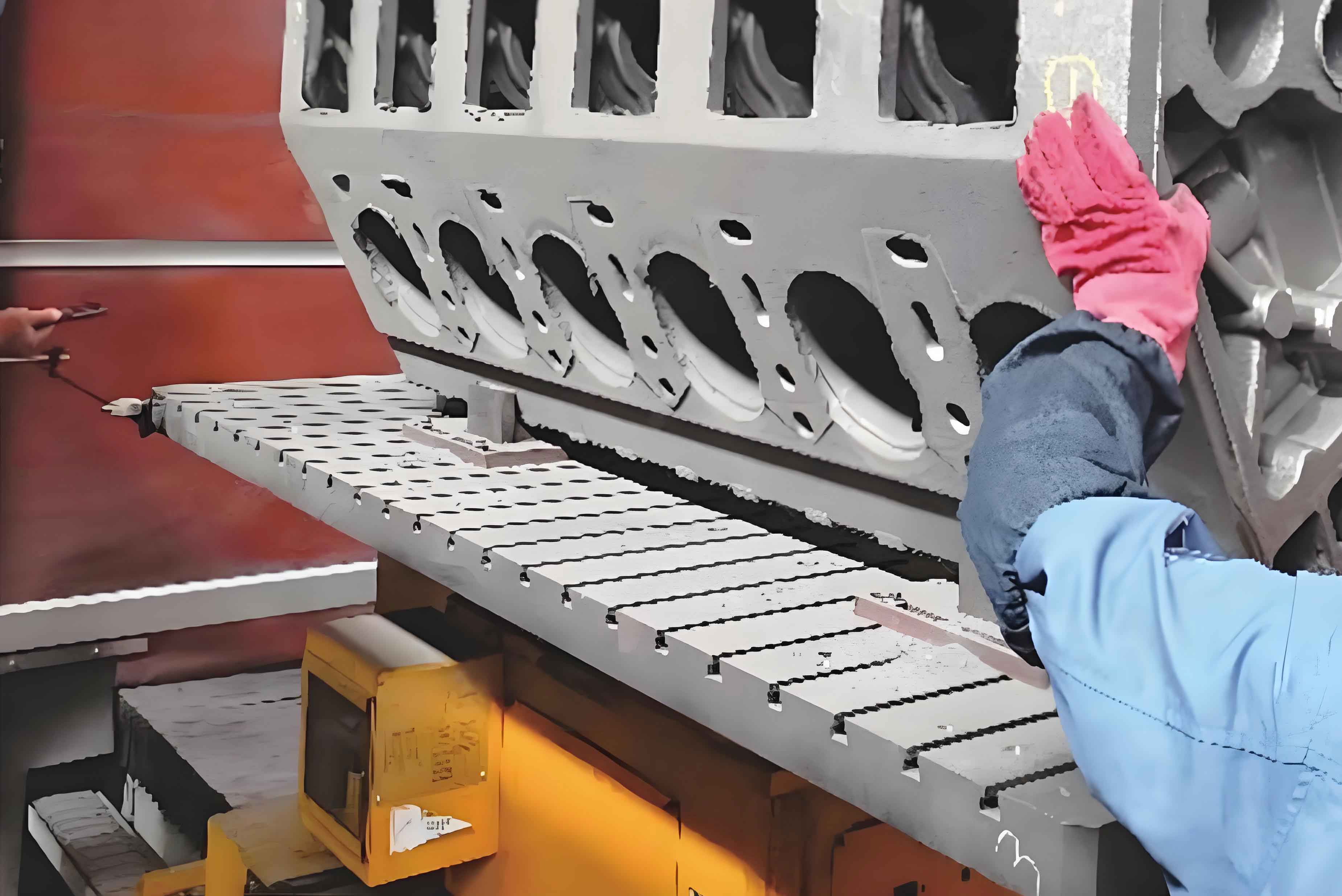
The leakage box defect is located at the flange of the gear cavity on the rear end face of the cylinder block. The appearance of the casting is incomplete, and the defect shows a hollow – shell – like shape, as shown in Figure 1. This defect not only affects the appearance of the product but also may lead to problems such as oil leakage during the operation of the engine, seriously affecting the performance and reliability of the engine.
3.1.2 Cause Analysis
The fluidity of compacted graphite cast iron is stronger than that of gray cast iron. In the case of the 8Y cylinder block, the gear cavity part is far from the pouring cup, and the defect location is at the highest point during pouring. These factors make it easy to form defects such as misruns or leakage boxes. Through process tracking and analysis, it is found that there is an eccentric problem after core – setting. This causes local gaps between the cores to be too large. During pouring, molten iron leaks from these gaps, which is the main cause of the leakage box defect.
3.2 Shrinkage Defect
3.2.1 Defect Description
The shrinkage defect is located at the thick – section area between two cylinder bores of the cylinder block. It presents as concentrated small holes, and the defect area is significantly different from the normal cross – section, as shown in Figure 2. Shrinkage defects can reduce the mechanical strength of the casting in the defect area, affecting the overall performance and service life of the cylinder block.
3.2.2 Cause Analysis
Compacted graphite cast iron solidifies in a “mushy” manner. When the thick – large hot spot solidifies, if there is no sufficient molten iron supply, shrinkage defects are likely to form. In addition, the original pouring temperature of (1430±10)°C is on the high side, and the carbon equivalent (CE = 4.25 – 4.58) is on the low side. These conditions contribute to the formation of shrinkage defects. High pouring temperatures increase the shrinkage tendency of the molten iron during solidification, while low carbon equivalents affect the graphite precipitation and compensation during solidification, resulting in insufficient material to fill the shrinkage space.
4. Optimization and Improvement Measures
4.1 Solutions for Leakage Box Defect
4.1.1 Calibration of Core – Setting Fixture
By adjusting the parameters of the core – setting equipment and the positioning points of the core – setting fixture, the core – setting position can be calibrated. This ensures that the sand cores can be accurately placed in the mold cavity, reducing the eccentricity problem. As a result, the local gaps between the cores are minimized, preventing molten iron from leaking during pouring.
4.1.2 Blocking of Leakage Risk Points between Sand Mold and Sand Core
Fire – resistant gaskets are placed at the leakage risk points of the core. These gaskets block the leakage path of the molten iron, effectively preventing the occurrence of leakage box defects. As shown in Figure 3, the gaskets are installed at the appropriate positions between the gear cavity auxiliary sand core, the main sand core, and the lower sand mold.
4.2 Solutions for Shrinkage Defect
4.2.1 Reduction of Pouring Temperature
Reducing the pouring temperature is beneficial for reducing the shrinkage tendency of compacted graphite cast iron. The original pouring temperature of the product is (1430±10)°C, and after adjustment, it is changed to (1410±10)°C. Lowering the pouring temperature can slow down the solidification process of the molten iron, allowing more time for the molten iron to flow and fill the shrinkage space, thereby reducing the occurrence of shrinkage defects.
4.2.2 Regulation of Trace Element Content in Molten Iron
The content of trace elements in molten iron is adjusted to increase the carbon equivalent (CE). The content of C element in the original molten iron is increased from 3.60% – 3.80% to 3.78% – 3.85%, and the content of Si element is increased from 1.85% – 1.90% to 2.10% – 2.20%. At the same time, the content of Mn element is reduced from 0.40% – 0.50% to 0.30% – 0.40%. These adjustments promote the precipitation of graphite during solidification, which can compensate for the shrinkage volume to a certain extent, reducing the formation of shrinkage defects.
| Scheme Implementation | Pouring Temperature T/°C | Material Chemical Composition (w/%) | ||
|---|---|---|---|---|
| C | Si | Mn | ||
| Before Implementation | 1430±10 | 3.65 – 3.80 | 1.85 – 1.90 | 0.40 – 0.50 |
| After Implementation | 1410±10 | 3.78 – 3.85 | 2.10 – 2.20 | 0.30 – 0.40 |
5. Implementation Effects
5.1 Effect on Leakage Box Defect
Before the process optimization, the leakage box defect rate was 41.67%. After implementing the two measures of calibrating the core – setting fixture and blocking the leakage risk points, the leakage box defect rate dropped to 0%. The experimental results are shown in Table 1, and the defect improvement effect is shown in Figure 4.
| Whether Measures are Taken | Process Measure Content | Test Quantity (pieces) | Leakage Box (pieces) | Defect Rate (%) |
|---|---|---|---|---|
| No | None | 24 | 10 | 41.67 |
| Yes | Only Calibrate Core – Setting Fixture | 24 | 6 | 25.00 |
| Yes | Only Block Leakage Points | 24 | 1 | 4.17 |
| Yes | Implement Both of the Above Measures | 24 | 0 | 0.00 |
5.2 Effect on Shrinkage Defect
Before the process optimization, the shrinkage defect rate was 37.50%. After implementing the two measures of reducing the pouring temperature and adjusting the trace element content in the molten iron, the shrinkage defect rate in the sampling inspection dropped to 0%. The experimental results are shown in Table 2, and the defect improvement effect is shown in Figure 5.
| Whether Measures are Taken | Process Measure Content | Test Quantity (pieces) | Sampling and Dissection Quantity (pieces) | Shrinkage (pieces) | Defect Rate (%) |
|---|---|---|---|---|---|
| No | None | 24 | 8 | 3 | 37.50 |
| Yes | Only Reduce Wire – Feeding Treatment Temperature | 24 | 8 | 1 | 12.50 |
| Yes | Only Adjust Trace Elements in Original Molten Iron | 24 | 8 | 1 | 12.50 |
| Yes | Implement Both of the Above Measures | 24 | 8 | 0 | 0.00 |
6. Generalization and Extension of Defect – Solving Methods
6.1 Application in Similar Casting Projects
The methods of calibrating the core – setting fixture and blocking the leakage risk points between the sand mold and the sand core to solve the leakage box defect can be applied to other casting projects with similar structures and processes. In general, for casting products with complex core structures and potential leakage problems, these two measures can effectively improve the casting quality. By accurately controlling the core – setting position and blocking the leakage paths, the occurrence of leakage box – like defects can be minimized.
For the shrinkage defect solution, although the use of heating and insulating risers and chills is a more common method in general casting, when the defect location is not convenient for conventional operations, adjusting the pouring temperature and trace element content in the molten iron can be a practical alternative. This method can be extended to other casting projects using compacted graphite cast iron or similar materials, especially when dealing with shrinkage defects in thick – walled parts.
6.2 Significance for the Development of the Casting Industry
The successful resolution of casting defects in the 8Y diesel engine cylinder block project has important guiding significance for the development of the casting industry. It provides practical experience for the large – scale and stable production of compacted graphite cast iron products. Compacted graphite cast iron has excellent comprehensive properties, but its casting process is difficult. By mastering effective defect – solving methods, the casting industry can improve the production efficiency and product quality of high – performance casting products, reduce production costs, and enhance the competitiveness of products in the market. This is also conducive to promoting the application and development of advanced materials in the casting field, driving the technological innovation and development of the entire casting industry.
7. Conclusion
In the development process of the 8Y diesel engine cylinder block, casting defects such as leakage boxes and shrinkage holes have been encountered. Through in – depth analysis of the causes of these defects and the implementation of corresponding optimization measures, significant results have been achieved. The leakage box defect rate has dropped from 41.67% to 0%, and the shrinkage defect rate has dropped from 37.50% to 0%.
The methods of calibrating the core – setting fixture and blocking the leakage risk points between the sand mold and the sand core are effective in solving the leakage box defect. Adjusting the pouring temperature and trace element content in the molten iron can effectively solve the shrinkage defect. These methods can be used as references for solving similar problems in other casting projects.
Compacted graphite cast iron has excellent comprehensive properties, but its casting process is complex. To achieve large – scale and stable production, it is necessary to strictly consider every link in the casting process. In future research and production, continuous exploration and improvement of casting processes and defect – solving methods are needed to promote the development of high – performance casting products.