
In the production of heavy steel castings, such as mill housings, the occurrence of internal and surface discontinuities remains a significant challenge. Among these, defects colloquially and technically referred to as ‘casting holes’—primarily sand inclusions and slag entrapments—are particularly prevalent and damaging. Through extensive hands-on experience in producing hundreds of such critical components, I have observed that these ‘casting holes’ are often the root cause of extensive, costly, and time-consuming weld repairs. Their prevention is not merely a matter of cost reduction and schedule adherence but is fundamentally linked to enhancing the structural integrity and reliability of the final product. While advanced simulation technologies have largely solved issues related to shrinkage and porosity, the consistent elimination of these common ‘casting holes’ requires a deep, practical understanding of the entire process flow. This analysis synthesizes observations on the morphology, root causes, and, most importantly, the effective preventive measures for these defects, forming a comprehensive strategy for quality assurance.
1. Sand Inclusions: Morphology, Origins, and Countermeasures
Sand inclusions manifest as cavities filled with or associated with loose or sintered sand particles. Their characteristics can be summarized as follows:
| Feature | Description |
|---|---|
| Morphology | Single, isolated cavities or dense clusters of defects. |
| Primary Location | Predominantly on the upper (cope) surfaces of the casting. Secondary locations include side walls and bottom drag surfaces, usually as single defects. |
| Severity Classification | Classified as a Major Defect if any single criterion is met: Depth ≥ 50 mm, Length ≥ 300 mm, or Volume ≥ 1000 cm³. Clustered defects typically exceed these limits after removal. |
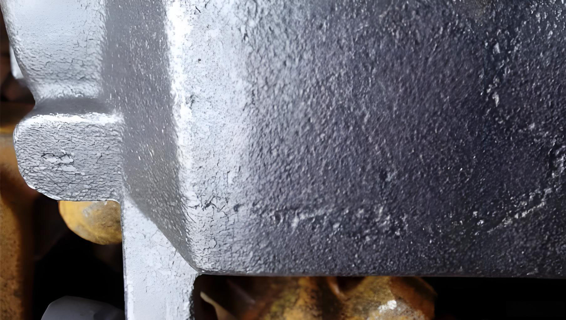
The visual evidence clearly shows the typical appearance of such surface discontinuities, underscoring the need for effective prevention strategies. The formation of these ‘casting holes’ is not random but stems from specific process stages.
1.1 Root Cause Analysis for Sand Inclusions
The genesis of sand-related ‘casting holes’ can be traced to three principal sources:
| Source | Mechanism | Contribution to ‘Casting Holes’ |
|---|---|---|
| Ladle Refractory & Tundish Sand | Large castings require multiple ladles. Each ladle nozzle (e.g., 80 mm diameter) is filled with ~90 kg of chrome-based tundish sand to initiate flow. Despite using skim plates, significant amounts enter the mold. | Primary Contributor. High-volume, exogenous material directly introduced into the metal stream. |
| Gating System Contamination | Long, multi-section ceramic gating systems used in tandem pouring have numerous joints and internal surfaces where loose molding sand can accumulate. | Secondary Contributor. Lower volume but still capable of creating isolated ‘casting holes’. |
| Cope Mold Erosion/Collapse | Intense thermal radiation during filling causes cope sand to expand, lose strength, and spall. Small particles float to the top; large chunks may become trapped. | Significant Contributor. Directly related to the cope mold’s thermo-mechanical stability. |
The total mass of foreign sand entering the mold cavity \(M_{total}\) can be conceptually modeled as:
$$M_{total} = M_{ladle} + M_{gating} + M_{cope}$$
where \(M_{ladle}\) is the mass of tundish sand, \(M_{gating}\) is contamination from the gating system, and \(M_{cope}\) is eroded cope sand. Minimizing each term is critical to preventing these ‘casting holes’.
1.2 Preventive Measures for Sand Inclusions
A multi-faceted approach is required to tackle the different sources of sand inclusions.
1.2.1 Gating System Design for Flotation: Research on fluid dynamics during filling indicates that a well-designed step-gating system is superior to a single-level gating for slow pours. The upper ingates introduce hotter metal into the upper parts of the cavity, maintaining a favorable temperature gradient for flotation. More importantly, the upper sections of the gating act as effective slag and sand traps. Empirical observation confirms that the upper runner often contains a concentration of collected tundish sand, preventing it from entering the casting cavity and becoming ‘casting holes’.
1.2.2 Enhancing Cope Mold Integrity: To prevent cope sand collapse—a direct cause of large ‘casting holes’—the following measures are essential:
- Reinforcement with Steel Mesh: A layer of steel rebar mesh is embedded approximately 15-20 mm beneath the casting face of the cope mold. This mesh is securely wired to the core’s structural frame, dramatically increasing the cohesion and resistance to spalling under thermal stress.
- Superior Mold Material: The face sand for the cope is formulated as a chromite-based, silicate-bonded self-setting sand. Compared to conventional CO₂-silicate sand, this material offers significantly higher, more uniform strength and better thermal stability, reducing the source term \(M_{cope}\).
1.2.3 Process Discipline: Meticulous attention to the assembly of the gating system is non-negotiable. Every ceramic tube section and joint must be cleaned and inspected to minimize \(M_{gating}\).
2. Slag Entrapments: Formation and Strategic Prevention
Slag holes are cavities containing non-metallic, slag-like inclusions, distinctly different from sand-related ‘casting holes’.
| Feature | Description |
|---|---|
| Morphology & Location | Almost exclusively appear as dense clusters on the upper surfaces of the casting. Depth typically ranges from 20-50 mm, often exceeding machining allowances. |
| Severity | Due to their clustered nature and volume, they almost always qualify as Major Defects, requiring extensive excavation and repair. |
| Composition | Chemical analysis identifies the material as ladle refining slag (reducing slag), confirming its origin. |
2.1 Root Cause Analysis for Slag Entrapments
The steel for these castings undergoes rigorous refining (EAF, LF, wire feeding), achieving high purity. Therefore, the slag causing these ‘casting holes’ is not inherent but is introduced during the transfer. The primary mechanism is vortex formation during ladle teeming.
As the ladle empties, a vortex funnel forms above the nozzle. When the metal level falls below a critical height \(h_c\), this vortex can suck slag floating on top of the metal into the discharge stream. The entrained slag is then carried into the mold. The tendency for vortex formation and slag entrainment is governed by factors like nozzle diameter and pour rate. A simplified critical height can be related to flow parameters:
$$ h_c \propto \frac{Q}{\omega d^2} $$
where \(Q\) is the volumetric flow rate, \(\omega\) is the angular velocity of the vortex, and \(d\) is the nozzle diameter. Higher \(Q\) and larger \(d\) promote earlier and stronger vortex formation.
This explains a critical trade-off: While “low-temperature, fast-pouring” (high rise speed >6 mm/s) is traditionally favored for feeding and structure, it necessitates larger nozzles. Larger nozzles increase both tundish sand volume (\(M_{ladle}\)) and the risk of slag vortex formation, thereby increasing both types of ‘casting holes’.
2.2 Preventive Measures for Slag Entrapments
The strategy focuses on process control to avoid the conditions that lead to slag entrainment.
2.2.1 Optimized Pouring Parameters – “Medium-Temperature, Controlled Pouring”: We advocate shifting from “low-temperature, fast-pouring” to a more balanced regime.
| Parameter | Traditional “Fast Pour” | Proposed “Controlled Pour” | Rationale |
|---|---|---|---|
| Pouring Temperature | ~1540°C | 1550°C – 1560°C | Higher temperature lowers metal viscosity, enhancing the flotation velocity of both slag and sand particles according to Stokes’ Law, aiding their removal before solidification and preventing ‘casting holes’. |
| Rise Speed in Mold | >6 mm/s | 3 mm/s – 4 mm/s | Reduced flow rate allows for the use of smaller nozzles, decreasing vortex strength and slag entrainment risk. The step-gating system compensates for thermal gradients. |
The flotation velocity \(v_f\) of a spherical inclusion is given by Stokes’ Law:
$$ v_f = \frac{2}{9} \cdot \frac{g r^2 (\rho_m – \rho_i)}{\eta} $$
where \(g\) is gravity, \(r\) is inclusion radius, \(\rho_m\) and \(\rho_i\) are densities of metal and inclusion, and \(\eta\) is metal viscosity. Higher temperature decreases \(\eta\), directly increasing \(v_f\), giving inclusions more time to float out.
2.2.2 Critical Pour Termination Practice: The most direct operational control is vigilant monitoring of the teeming stream. The moment the stream from the ladle nozzle begins to weaken and “flare” or “flutter”, it signals that the metal level is low and slag is being drawn toward the vortex. Pouring must be stopped immediately, even if it means retaining a significant heel of steel in the ladle. This single discipline is paramount in preventing the catastrophic influx of slag that creates massive clusters of ‘casting holes’.
3. Synthesis: An Integrated Preventive Framework
The prevention of ‘casting holes’ is not a single-action solution but a system of interdependent controls. The following table synthesizes the complete strategy, linking causes to specific, actionable measures.
| Defect Type (‘Casting Holes’) | Primary Cause | Integrated Preventive Measures | Expected Outcome |
|---|---|---|---|
| Sand Inclusions | Ladle Tundish Sand | 1. Use of step-gating system as a primary trap. 2. Controlled pour rate to minimize initial sand intake. |
Drastic reduction in sand-related cavities, minimizing repair volume and moving towards “no-repair” castings. |
| Gating System Sand | 3. Meticulous cleaning and assembly of all gating components. | ||
| Cope Sand Collapse | 4. Reinforcement of cope mold with steel mesh. 5. Use of high-strength chromite self-setting sand for the cope face. |
||
| Slag Entrapments | Ladle Slag Vortex | 6. Adopt “Medium-Temperature, Controlled Pouring” (1550-1560°C, 3-4 mm/s rise speed). 7. Implement strict pour termination at the first sign of stream flare. |
Elimination of major slag hole clusters, transforming a major quality issue into a rare occurrence. |
| Poor Slag Flotation | 8. Higher pouring temperature enhances flotation per Stokes’ Law. 9. Step-gating maintains favorable thermal gradient for flotation to the upper reservoirs. |
3.1 The Role of Thermal Management
The advocated “medium-temperature” approach warrants further explanation. The goal is to find the optimum that balances fluidity for feeding and inclusion flotation against the risks of gross segregation and excessive grain growth. The thermal history can be conceptualized using the Fourier heat conduction equation, where the initial condition \(T_{pour}\) is crucial:
$$ \frac{\partial T}{\partial t} = \alpha \nabla^2 T $$
where \(\alpha\) is thermal diffusivity. A higher \(T_{pour}\) provides a greater thermal buffer, delaying solidification at the cope surface and extending the time window \(t_f\) available for inclusions to float out before being trapped by the advancing solidus front. This directly reduces the probability \(P_{trap}\) of forming ‘casting holes’:
$$ P_{trap} \propto \exp\left(-\frac{t_f}{t_{flot}}\right) $$
where \(t_{flot}\) is the flotation time required for an inclusion to reach a safe sink (e.g., a feeder or the upper runner). Increasing \(T_{pour}\) increases \(t_f\), thereby decreasing \(P_{trap}\).
4. Conclusion
The persistent challenge of ‘casting holes’ in heavy steel castings demands a holistic and analytical approach. Through systematic deconstruction of the defect formation mechanisms—distinguishing between sand-driven and slag-driven ‘casting holes’—targeted and effective countermeasures have been developed and validated in production. The cornerstone of this strategy is the abandonment of the simplistic “fast-pour” dogma in favor of a nuanced “controlled-pour” methodology, synchronized with robust gating design and mold engineering. The implementation of a step-gating system, coupled with rigorous cope mold reinforcement and disciplined pouring practices (including precise temperature control and mandatory early teeming termination), forms an integrated defense system. This framework directly attacks the root causes of these defects, significantly reducing the incidence of both isolated and clustered ‘casting holes’. The result is a dramatic improvement in casting soundness, leading to a substantial reduction in repair costs, shorter manufacturing cycles, and, most importantly, the production of mill housings and similar heavy castings with enhanced and more reliable metallurgical quality. The battle against ‘casting holes’ is won not by a single technological breakthrough but by the meticulous application of physics-based principles across the entire casting process chain.