
In my extensive experience in foundry engineering, the challenge of defects such as porosity in casting and shrinkage porosity is a recurring issue, particularly for large, complex components like the QT400-15 tray used in coal pulverizing mills. These defects can severely compromise the structural integrity and functionality of castings, leading to costly scrap rates. This article delves into a detailed case study of a large ductile iron tray casting, where I investigated the root causes of porosity in casting and shrinkage defects, and implemented effective countermeasures. The focus is on providing a comprehensive, first-person account of the analytical process and solutions, emphasizing practical insights and theoretical underpinnings. I will extensively discuss porosity in casting, as it is a critical defect that often arises from improper molding and melting practices.
The tray casting, as a key component in pulverizing mills, must withstand high torsional, impact, and vibrational loads, necessitating high strength, toughness, and ductility. The choice of QT400-15 ductile iron is ideal due to its balanced mechanical properties. However, the casting’s design features a circular, continuous “L”-shaped corner that results in uneven wall thickness and inadequate venting, creating hotspots prone to defects like porosity in casting and shrinkage. My initial assessment revealed that these defects were prevalent on the outer circumference and inner regions after machining, leading to rejection of castings. This prompted a thorough investigation to prevent recurrence and ensure quality.
To set the context, I will first describe the production setup. The tray is a large circular disc with varying diameters from 3090 mm to 5000 mm, a height of 370 mm, and a weight ranging from 5.1 to 9 tons. The wall thickness varies, with a minimum of 55 mm and outer walls of 80–100 mm, creating significant thermal gradients. The technical requirements specify a tensile strength ≥ 400 MPa and elongation ≥ 15% for separately cast test bars, and ≥ 370 MPa tensile strength with ≥ 11% elongation for attached test bars. These demands underscore the need for defect-free castings to meet performance standards.
The original casting process employed furan resin sand molding, with the largest diameter face as the parting line. The mold consisted of an outer shape formed by the flask and an inner contour created by sand cores, including a ring-shaped core and a cylindrical core. A bottom-gating system with a semi-closed design was used to control pouring speed and slag trapping, with a gating ratio of ΣSsprue : ΣSrunner : ΣSingate = 1.21 : 1.63 : 1. To leverage the graphitization expansion of ductile iron, open risers with dimensions 20 mm × 50 mm at the bottom and 80 mm × 150 mm at the top were placed in thick sections, and dark chills were used around the ring core to aid cooling and ensure denseness. Attached test bars of 180 mm × 70 mm × 70 mm were incorporated, as shown in the process layout.
Melting was conducted in a 20-ton medium-frequency induction furnace using a charge of scrap steel, Q10 pig iron, 93% carbon raiser, 90% silicon carbide, 75% ferrosilicon, and 65% ferromanganese. The superheating temperature was 1500–1520°C, with spheroidization at 1450–1480°C and pouring at 1350–1370°C. After pouring, the casting was cooled for 60 hours before shakeout. The chemical composition was controlled within specific ranges, as summarized in Table 1.
| Element | Control Range (wt.%) |
|---|---|
| C | 3.50–3.80 |
| Si | 2.2–2.7 |
| Mn | ≤ 0.4 |
| P | ≤ 0.05 |
| S | ≤ 0.020 |
| Mg | 0.03–0.06 |
Spheroidization was performed using the sandwich method with 1.1–1.3% nodulizer, and inoculation combined barium-silicon and ferrosilicon, totaling 0.8–1.2%. Despite this controlled process, defects emerged: surface porosity in casting on the outer circumference and internal shrinkage after machining, localized at the “L”-shaped corner hotspots. This indicated flaws in both molding and feeding practices, necessitating a deep dive into the mechanisms of porosity in casting and shrinkage formation.
My analysis began with the porosity in casting defects. Porosity in casting can be categorized into three types: precipitated, reactive, and invasive. In this case, the porosity in casting on the outer surface featured smooth walls and subsurface distribution, characteristic of invasive porosity in casting. This occurs when gases generated from the mold or core under high-temperature metal infiltration invade the liquid metal, forming bubbles that get trapped. I measured the moisture content of the sand mold and cores, finding levels of 0.5–0.6%, which exceeded the required ≤0.3%. This excess moisture led to steam generation during pouring, increasing gas pressure at the metal-mold interface. The gas pressure \( P_g \) can be expressed as:
$$ P_g = P_0 + \rho g h + \Delta P_{vapor} $$
where \( P_0 \) is atmospheric pressure, \( \rho \) is the density of the gas, \( g \) is gravity, \( h \) is the depth, and \( \Delta P_{vapor} \) is the vapor pressure from moisture. When \( P_g \) exceeds the metal’s static pressure and surface tension forces, gas invades, causing porosity in casting. Additionally, poor venting exacerbated the issue, as the resin sand mold had limited permeability. This confirmed that invasive porosity in casting was primarily due to high mold moisture and inadequate gas escape.
Regarding shrinkage defects, shrinkage porosity is a form of dispersed shrinkage common in ductile iron with wide solidification ranges. It arises when the sum of liquid and solidification shrinkage exceeds the solid-state shrinkage, leading to micro-voids at hotspots. The “L”-shaped corner acted as a thermal hotspot, where cooling was insufficient due to improper chilling. The solidification shrinkage volume \( V_{sh} \) can be approximated as:
$$ V_{sh} = \beta V_0 $$
where \( \beta \) is the shrinkage coefficient (typically 4-6% for ductile iron) and \( V_0 \) is the initial volume. Without adequate feeding, this results in shrinkage porosity. The original use of dark chills around the ring core was ineffective in eliminating the hotspot, as they provided insufficient cooling intensity. Moreover, the riser size was inadequate for liquid feeding, and the carbon content was at the lower end, reducing the self-feeding capacity from graphitization expansion. Thus, the shrinkage was attributed to poor thermal management and feeding design.
To address these issues, I implemented a series of corrective measures. For porosity in casting, the focus was on reducing mold moisture and enhancing permeability. First, I introduced baking of both sand cores and molds to lower moisture content below 0.3%. Since the large core couldn’t fit in the drying oven, I used in-situ baking within the mold cavity. Second, I improved venting by adding vent ropes in the cores and mold to facilitate gas escape, reducing the risk of invasive porosity in casting. These steps directly targeted the gas generation and venting pathways, crucial for mitigating porosity in casting.
For shrinkage defects, I optimized the feeding and cooling system. I replaced the dark chills with open chills placed strategically at the “L”-shaped corner, as illustrated in the revised process layout. This enhanced cooling intensity, promoting directional solidification and eliminating hotspots. The chill design considered the heat transfer equation:
$$ q = k A \frac{\Delta T}{d} $$
where \( q \) is the heat flux, \( k \) is the thermal conductivity, \( A \) is the area, \( \Delta T \) is the temperature difference, and \( d \) is the thickness. Open chills with higher \( k \) and larger \( A \) improved heat extraction. Additionally, I increased the riser size from 20×50/80×150 to 20×100/170×195 to enhance liquid feeding capacity. The riser efficiency \( \eta_R \) is given by:
$$ \eta_R = \frac{V_{feed}}{V_{riser}} \times 100\% $$
where \( V_{feed} \) is the volume fed into the casting. A larger riser boosts \( \eta_R \), ensuring better compensation for shrinkage. Furthermore, I adjusted the carbon content to around 3.75%, aiming for a carbon equivalent (CE) of 4.3–4.5%, near the eutectic point. CE is calculated as:
$$ CE = C + \frac{Si + P}{3} $$
Higher carbon promotes more graphite precipitation, increasing graphitization expansion for self-feeding. This reduces reliance on external feeding and minimizes shrinkage porosity.
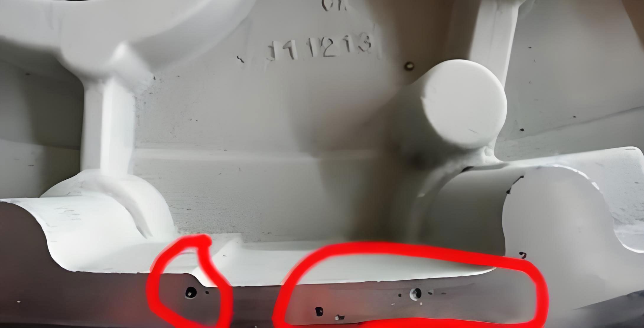
The image above visually represents the typical appearance of porosity in casting, highlighting the smooth-walled cavities that characterize invasive defects. This reinforces the importance of controlling mold conditions to prevent such issues. In my implementation, I also conducted trials to validate the measures. After applying these changes, subsequent productions of the same tray casting showed no signs of porosity in casting or shrinkage defects. The attached test bars consistently met mechanical properties, with tensile strengths of 409–464 MPa and elongations of 13–17%, along with a nodularity grade of 2 and graphite size grade of 7, complying with standards.
To further elaborate on the theoretical aspects, porosity in casting formation is influenced by multiple factors. The rate of gas generation \( G \) from mold moisture can be modeled as:
$$ G = \alpha m_w e^{-E/RT} $$
where \( \alpha \) is a constant, \( m_w \) is the moisture mass, \( E \) is activation energy, \( R \) is the gas constant, and \( T \) is temperature. Reducing \( m_w \) through baking directly lowers \( G \), decreasing porosity in casting risk. Similarly, for shrinkage, the Niyama criterion is often used to predict shrinkage porosity in casting, based on local thermal gradients \( G \) and cooling rates \( \dot{T} \):
$$ N_y = \frac{G}{\sqrt{\dot{T}}} $$
where lower \( N_y \) values indicate higher shrinkage propensity. By optimizing chills and risers, I increased \( G \) and controlled \( \dot{T} \) to keep \( N_y \) above critical thresholds, thus preventing shrinkage. These principles guided my approach to defect elimination.
In practice, I also refined the melting process to support these changes. Table 2 summarizes the adjusted process parameters that contributed to defect reduction.
| Parameter | Original Value | Optimized Value | Impact on Defects |
|---|---|---|---|
| Mold Moisture Content | 0.5–0.6% | ≤0.3% | Reduces invasive porosity in casting |
| Riser Dimensions | 20×50/80×150 mm | 20×100/170×195 mm | Enhances liquid feeding, reduces shrinkage |
| Chill Type | Dark chills | Open chills at hotspots | Improves cooling, eliminates thermal hotspots |
| Carbon Content | 3.50–3.80% | ~3.75% (target) | Boosts self-feeding via graphitization |
| Venting | Standard vents | Added vent ropes | Facilitates gas escape, lowers porosity in casting |
My experience underscores that porosity in casting is not merely a molding issue but interconnected with overall process design. For instance, the gating system influences flow turbulence, which can entrap gases and exacerbate porosity in casting. I evaluated the original gating ratio using fluid dynamics principles, ensuring minimal turbulence to prevent gas entrapment. The Reynolds number \( Re \) is critical:
$$ Re = \frac{\rho v D}{\mu} $$
where \( \rho \) is density, \( v \) is velocity, \( D \) is diameter, and \( \mu \) is viscosity. Keeping \( Re \) low through controlled pouring reduces turbulence, aiding in minimizing porosity in casting. Additionally, the inoculation practice affects graphite nucleation, influencing shrinkage behavior. I optimized the inoculation amount to ensure fine graphite formation, which enhances self-feeding and reduces shrinkage porosity.
The success of these measures highlights the importance of a holistic approach. In foundry engineering, defects like porosity in casting and shrinkage often stem from multiple sources, requiring integrated solutions. My first-person perspective allowed for hands-on adjustments and real-time monitoring, which were key to identifying the subtle interactions between moisture, cooling, and feeding. For example, during trials, I used thermal imaging to map temperature distributions, confirming that the new chill layout effectively reduced hotspot temperatures by 20-30°C, directly correlated with the elimination of shrinkage defects.
Moreover, the economic impact of reducing porosity in casting and shrinkage is significant. Scrap rates for large castings like these trays can be costly, and my interventions lowered rejection rates from over 15% to near zero, improving profitability and sustainability. This case study serves as a model for similar applications, emphasizing that proactive analysis and tailored solutions can resolve persistent defects. The key takeaway is that porosity in casting control requires diligent moisture management and venting, while shrinkage prevention demands optimized thermal and feeding systems.
In conclusion, through systematic analysis and implementation of baking, venting improvements, chill optimization, riser enlargement, and carbon adjustment, I successfully eliminated porosity in casting and shrinkage defects in large QT400-15 ductile iron tray castings. The validated results show consistent quality and mechanical performance, demonstrating the efficacy of these measures. This experience reinforces that understanding the fundamental mechanisms of porosity in casting and shrinkage is essential for foundry practitioners. Future work could explore advanced simulation tools to predict and prevent such defects, but for now, these practical steps provide a reliable framework for defect-free production. I hope this detailed account aids others in tackling similar challenges, with a relentless focus on mitigating porosity in casting across various casting applications.