
In the production of large, structurally complex ductile iron castings, the occurrence of defects such as porosity and shrinkage remains a significant challenge that directly impacts the integrity, mechanical properties, and service life of the final component. This article details our first-hand investigation and resolution of persistent quality issues encountered in the manufacture of large tray castings, specifically designed for coal mill applications. The component in question, a substantial annular structure with pronounced “L”-shaped junctions, exhibited severe subsurface porosity and internal shrinkage porosity in critical sections. Through systematic analysis and targeted process modifications, we successfully eliminated these defects. The following discussion outlines the problem, our diagnostic approach rooted in casting metallurgy, and the effective countermeasures implemented, supported by relevant data and theoretical principles.
The tray casting is a critical load-bearing component within a coal mill. Its primary function is to support the grinding process where raw coal is pulverized into fine powder to enhance combustion efficiency. Consequently, the material must exhibit a favorable combination of strength, ductility, and wear resistance, making the ferritic grade QT400-15 (with a minimum tensile strength of 400 MPa and 15% elongation) the ideal choice. However, the very geometry that defines its function also predisposes it to casting defects. The structure is essentially a large annular disc with an integrated vertical flange, creating continuous “L”-shaped thermal junctions around its entire circumference. This design leads to significant variations in wall thickness and creates regions prone to inadequate feeding and gas entrapment during solidification.
The initial production process for these trays was as follows. The mold was created using furan resin-bonded sand. The parting plane was set at the casting’s maximum diameter. The outer contour was formed by the cope mold, while the inner contour and central hub were formed by assembled sand cores. A bottom-gating system was employed with a semi-open ratio to ensure a calm filling sequence and effective slag trapping. The gating ratio was ΣSsprue : ΣSrunner : ΣSingate = 1.21 : 1.63 : 1. To harness the graphitization expansion characteristic of ductile iron and to aid feeding, multiple blind risers (exothermic sleeves) were placed on the thicker sections of the top surface. Additionally, external chill plates were positioned against the outer wall of the annular core to promote directional solidification. The melting was conducted in a medium-frequency induction furnace, with a base charge of 60% steel scrap and 40% pig iron. The target chemical composition is summarized in Table 1.
| Element | C | Si | Mn | P | S | Mg |
|---|---|---|---|---|---|---|
| Range | 3.50 – 3.80 | 2.2 – 2.7 | ≤ 0.40 | ≤ 0.05 | ≤ 0.020 | 0.03 – 0.06 |
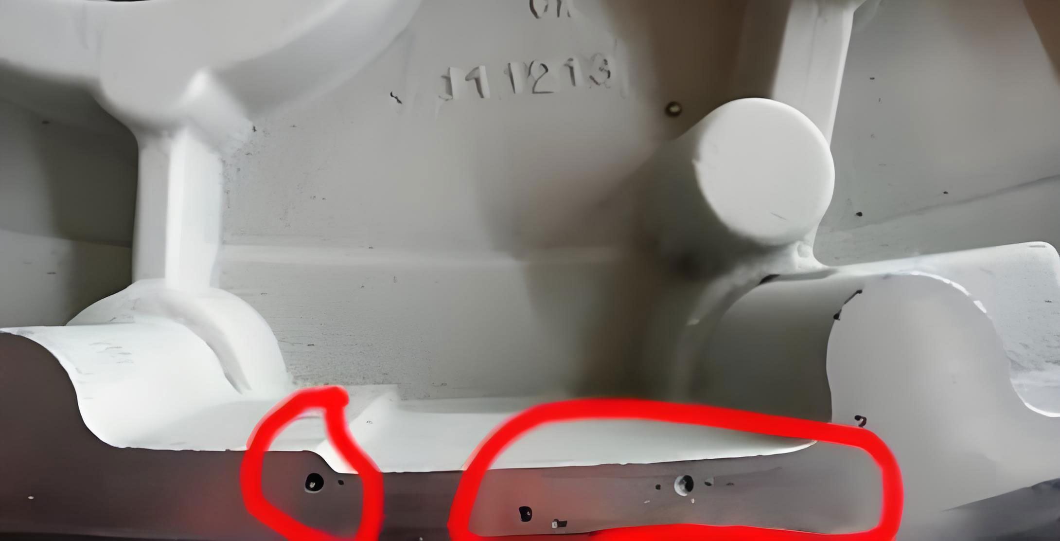
Post-casting analysis of components produced via this initial method revealed two primary, recurring defects. The first was a band of finely distributed, smooth-walled pores located just beneath the skin on the upper surface of the casting’s outer rim. The second defect was internal shrinkage porosity, manifesting as a spongy, interconnected network of micro-voids, which was only revealed after machining the inner “L”-section junction. These defects are classical examples of casting imperfections that compromise pressure tightness and fatigue strength.
Root Cause Analysis of Defects
1. Investigation of Porosity in Casting
The formation of porosity in casting can be attributed to three fundamental mechanisms: precipitation, reaction, and invasion. A careful examination of the defect’s characteristics—its subsurface location, fine distribution, and smooth, shiny appearance—pointed decisively towards reaction-type porosity, often termed “pinhole” or “subsurface porosity.”
This form of porosity in casting occurs due to a chemical reaction at the metal-mold interface. In green sand or chemically bonded molds with residual moisture, the high-temperature molten iron reacts with water vapor to produce hydrogen gas:
$$ \text{Fe} + \text{H}_2\text{O} \rightarrow \text{FeO} + 2\text{H} $$
The nascent hydrogen atoms can either dissolve into the molten iron or form molecular hydrogen bubbles at the interface. Given the high solidification rate of the surface layer, these bubbles become trapped just beneath the solidified skin. The susceptibility to this defect increases exponentially with mold moisture content and the presence of elements like aluminum or magnesium that increase the melt’s oxidation potential. Our diagnosis concluded that despite using resin sand, the molds and cores likely contained excess moisture from ambient conditions or inadequate drying, providing the reactant for this hydrogen-based porosity in casting.
| Porosity Type | Typical Location & Morphology | Primary Cause | Governing Factors |
|---|---|---|---|
| Precipitation | Uniform, often near thermal centers; numerous small pores. | Decreased gas solubility during cooling. | Initial gas content in melt ($C_0$), cooling rate ($\dot{T}$). Solubility follows Sievert’s law: $S = k \sqrt{P}$. |
| Reaction (Subsurface) | Subsurface (1-3 mm), smooth, shiny, fine distribution. | Mold-metal reaction (e.g., Fe + H$_2$O). | Mold moisture, melt oxidation potential, poor venting. The reaction rate can be modeled as $R \propto [\text{H}_2\text{O}] \cdot e^{-E_a/RT}$. |
| Invasion | Large, few, located near top surfaces or core interfaces. | Gas from mold/core materials entering the melt. | Gas pressure in mold ($P_g$), metallostatic pressure ($\rho g h$). Invasion occurs if $P_g > \rho g h + \sigma / r$. |
2. Investigation of Shrinkage Porosity
Shrinkage porosity is a manifestation of inadequate liquid feeding during the latter stages of solidification. Ductile iron, with its wide solidification range due to the graphite eutectic, is particularly prone to forming dispersed micro-shrinkage rather than a single macro-shrimp cavity. The defect consistently appeared at the “L”-shaped junction, a classic thermal hot spot where two thick sections meet. This geometry creates a region that remains liquid longer than the surrounding material, becoming isolated from the liquid metal supply (the riser) as solidification progresses. The volume deficit from both liquid contraction and the phase change (austenite + liquid to austenite + graphite) then results in a porous, spongy structure.
The original use of external chills on the vertical flank was intended to shift this hot spot. However, analysis suggested the chilling effect was insufficient or improperly directed, failing to establish a effective temperature gradient toward the riser. Furthermore, the size and placement of the risers may have been inadequate to provide the necessary feed metal to this isolated thermal center during the critical period of solidification. The phenomenon can be conceptually related to the Niyama criterion for predicting shrinkage, which relates the temperature gradient $G$ and the cooling rate $\dot{T}$ at the end of solidification:
$$ N_y = \frac{G}{\sqrt{\dot{T}}} $$
Lower Niyama values indicate a higher risk of porosity in casting from shrinkage, typical of areas with low gradients and slow cooling—exactly the conditions in an under-chilled hot spot.
Implemented Corrective Actions and Metallurgical Rationale
Based on the above analysis, a multi-pronged strategy was deployed to simultaneously tackle the issues of reaction porosity in casting and shrinkage.
1. Measures to Eliminate Reaction Porosity in Casting
The core strategy was to eliminate the source of hydrogen and ensure any generated gases could escape easily.
- Mandatory Mold/Core Drying: A strict protocol was implemented to bake all large sand molds and cores prior to assembly and painting. The target was to reduce the volatile content (primarily moisture) in the mold surface layer to below 0.3%. This dramatically reduces the partial pressure of water vapor ($P_{H_2O}$) at the metal interface, shifting the reaction equilibrium and minimizing hydrogen generation.
- Enhanced Mold Venting: Vent channels were actively created by placing ceramic rope vents within the sand cores and against the mold walls. This provides low-resistance escape paths for gases, preventing pressure build-up that could force gases into the solidifying metal. The venting requirement can be approximated by ensuring the total vent area $A_v$ is sufficient for the gas generation rate: $A_v \propto V_m \cdot \dot{Q}_g / v_g$, where $V_m$ is mold volume, $\dot{Q}_g$ is gas generation rate, and $v_g$ is gas velocity.
- Optimized Riser Function: The existing blind risers were increased in size. While their primary function remained feeding, their larger mass also meant they stayed hotter longer, acting as effective thermal and pressure sinks, allowing gases from the casting cavity to be drawn upward and out through the riser permeability.
2. Measures to Eliminate Shrinkage Porosity
The strategy here focused on controlling solidification to eliminate the isolated hot spot and enhance feeding mechanisms.
- Redesign of Chilling Practice: The external chill plates were repositioned to directly target the root of the “L”-shaped junction. Furthermore, they were changed from “blind” chills (fully embedded in sand) to “open” or “direct” chills, ensuring intimate contact and maximum heat extraction. This aimed to create a steep thermal gradient, $G$, making the hot spot solidify directionally towards the riser, thereby eliminating the condition for dispersed shrinkage. The heat extraction can be modeled using the interface heat transfer coefficient $h_i$: $q = h_i (T_{melt} – T_{chill})$.
- Enhanced Liquid Feeding Capacity: As mentioned, the riser dimensions were significantly increased. The new design ensured a higher modulus (Volume/Surface Area ratio) for the riser compared to the hot spot modulus, guaranteeing it remained liquid long enough to feed the solidification shrinkage of the affected region. The required riser volume $V_r$ can be estimated from the casting shrinkage volume $V_s$ and riser efficiency $ε$: $V_r = V_s / ε$.
- Metallurgical Optimization for “Self-Feeding”: The carbon content was pushed toward the upper limit of the specification, targeting approximately 3.75%. This increases the Carbon Equivalent (CE = %C + (%Si+%P)/3), promoting a more eutectic solidification. A higher CE leads to a greater volume fraction of graphite precipitating during eutectic solidification. The associated volumetric expansion (graphitization expansion) can effectively counteract the shrinkage from the austenitic matrix, providing an internal “self-feeding” effect. This is a critical characteristic of ductile iron, described by:
$$ \Delta V_{graphite} \approx \text{(%Graphite)} \cdot \beta_{Fe-C} $$
where $\beta_{Fe-C}$ is the volumetric expansion coefficient for the graphite precipitation reaction.
Results and Validation
The implementation of these integrated corrective measures proved highly effective. In the subsequent production run of over 28 identical or geometrically similar tray castings, neither subsurface reaction porosity in casting nor internal shrinkage porosity was observed. The castings showed sound, dense metallographic structures at the previously problematic junctions.
Mechanical property testing was conducted on separately cast test coupons (as per standard foundry practice) to ensure the process changes did not adversely affect the material’s performance. The results, summarized in Table 3, demonstrate consistent achievement of the QT400-15 specification, with tensile strengths exceeding 400 MPa and elongation values ranging between 13% and 17%. The microstructures consistently showed ferritic matrix with well-nodularized graphite (Type I & II), confirming that the measures to prevent porosity in casting and shrinkage did not compromise graphite morphology or matrix structure.
| Sample Set | Avg. Tensile Strength (MPa) | Std. Dev. (MPa) | Avg. Elongation (%) | Std. Dev. (%) | Avg. Hardness (HBW) | Metallographic Consistency |
|---|---|---|---|---|---|---|
| Batch 1 (n=8) | 439.5 | 16.2 | 15.4 | 1.2 | 148 | Nodularity >85%, Ferrite >95% |
| Batch 2 (n=12) | 433.2 | 14.8 | 15.1 | 1.5 | 147 | Nodularity >85%, Ferrite >95% |
| Batch 3 (n=8) | 437.1 | 15.7 | 14.5 | 1.4 | 149 | Nodularity >85%, Ferrite >95% |
Conclusion
The successful resolution of defects in these large QT400-15 tray castings underscores the importance of a holistic approach to foundry problem-solving. The issues of reaction-based porosity in casting and shrinkage porosity, while distinct in origin, were interlinked through the casting’s geometry and process conditions. The key learning points are:
- Moisture Control is Paramount: For high-quality castings, especially in thick sections, controlling mold and core moisture is critical to prevent hydrogen-related reaction porosity in casting. Proactive drying is a simple yet highly effective countermeasure.
- Thermal Management Dictates Soundness: The strategic use of chills is not just about speeding up solidification, but about intelligently manipulating thermal gradients to eliminate isolated hot spots and direct solidification towards feeding sources.
- Leverage the Metallurgy of the Material: For ductile iron, optimizing the carbon content and CE to maximize the beneficial graphitization expansion is a powerful tool for achieving internal soundness, complementing external feeding mechanisms.
- Venting Cannot Be an Afterthought: Adequate and designed venting is essential to allow gases from all sources—mold reactions, core binders, or air displacement—to escape freely, preventing any form of entrapped gas porosity in casting.
By systematically addressing mold dryness, gas evacuation, solidification control, and metallurgical composition, we developed a robust and repeatable process. This case study demonstrates that persistent defects like subsurface porosity in casting and shrinkage in complex geometries can be reliably eliminated through rigorous analysis and targeted engineering of the entire casting process.