
In our foundry practice, addressing shrinkage in casting remains one of the most persistent and technically demanding challenges. This defect, particularly in nodular (ductile) iron, is a primary source of scrap and quality concerns. Nodular iron castings, predominantly of eutectic or hypereutectic composition, solidify in a mushy or pasty mode. This solidification characteristic means the developing casting skin often lacks the strength to fully resist the expansive forces generated during graphite precipitation. This can lead to mold wall movement, increasing the overall casting volume and creating internal voids that must be fed. Consequently, in the final regions to solidify—between dendrites and eutectic cells—the volumetric contraction cannot be fully compensated, leaving behind a network of micro- and macro-porosity known as shrinkage in casting. Therefore, the tendency for shrinkage in casting is inherently greater in nodular iron compared to gray iron, making it a particularly棘手 problem for foundry engineers.
Traditional methods for detecting internal shrinkage in casting include X-ray and ultrasonic inspection. However, X-ray analysis is often slow, costly, and poses radiation hazards to personnel. Ultrasonic testing, while useful, requires highly skilled operators for complex geometries and still carries a risk of missed defects. This case study details our systematic investigation and solution to a recurring internal shrinkage problem in a nodular iron cylinder head casting.
Casting Parameters and Initial Process
The subject component was a cylinder head with a nominal composition of QT450-10. Key production parameters are summarized in the table below:
| Parameter | Value / Description |
|---|---|
| Casting Dimensions | 144 mm x 106 mm x 81 mm |
| Casting Weight | 3 kg |
| Molding Process | DISA Vertical Flaskless Molding |
| Mold Configuration | 4 castings per mold (2 top, 2 bottom) |
| Total Poured Weight | 23 kg |
| Pouring Temperature Range | 1360 °C – 1380 °C |
| Pouring Time | 11.6 seconds |
The initial gating and feeding system employed top feeders (risers) located above specific sections of the casting, intended to compensate for solidification shrinkage.
Defect Manifestation and Root Cause Analysis
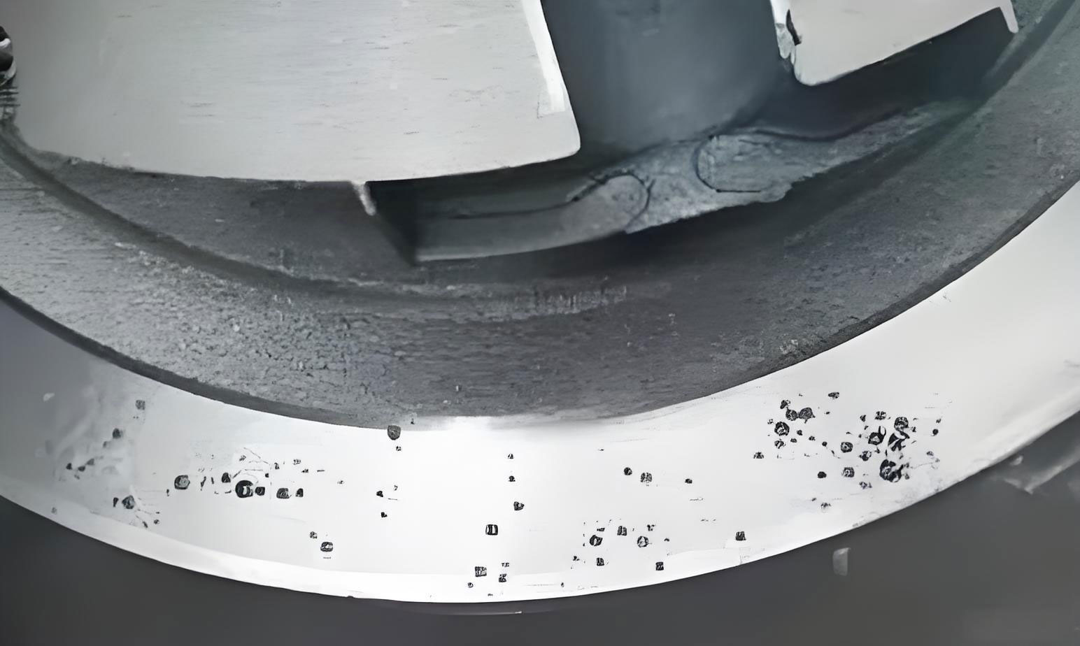
Following machining at the customer’s facility, internal porosity was detected. Non-destructive testing of 800 parts revealed 41 defective castings, corresponding to a scrap rate of 5.13%. The shrinkage in casting was consistently located within the internal passages of the upper oil gallery bosses on the top-row castings in the mold.
To diagnose the root cause, we employed MAGMAsoft solidification simulation software. The results were critical to our understanding:
- Thermal Analysis: The simulation clearly identified the problematic oil gallery boss as a significant thermal hotspot, indicating it was the last region to solidify within the casting body.
- Shrinkage Prediction: The porosity prediction module flagged this same location as having a high risk of macro-shrinkage in casting.
The simulation confirmed the empirical finding and focused our investigation. Through repeated production trials and mold inspections, we identified three interrelated primary causes for the shrinkage in casting defect:
| Root Cause Category | Specific Mechanism | Observed Consequence |
|---|---|---|
| Inadequate Riser Filling | Shallow pouring of the pouring cup to minimize spillage resulted in the horizontal runner being level with the top of the risers. | Risers were not completely filled with liquid metal, losing their feeding capacity before the critical section solidified. Approximately 21% of sampled top-row castings showed this issue. |
| Insufficient Riser Modulus & Feeding Path | The geometric modulus (Volume/Surface Area ratio) of the top risers was potentially marginal for the feeding demand of the thermal hotspot. | Even when filled, the risers solidified before the critical section, failing to provide adequate liquid feed metal to compensate for shrinkage in casting. Bottom-row castings were less affected, likely due to beneficial gravity feeding. |
| Poor Mold Venting | Inadequate escape paths for displaced air and gases from the mold cavity. | This caused slow metal flow (“slow pouring”) and back-pressure. The pouring cup metal level was observed to sink after initial filling, again contributing to unfilled or poorly filled risers. |
The fundamental relationship governing riser efficacy is based on Chvorinov’s Rule, where solidification time \( t \) is proportional to the square of the modulus \( M \):
$$ t = k \cdot M^n $$
where \( k \) is the solidification constant and \( n \) is approximately 2 for many castings. For a riser to be effective, its modulus must be greater than that of the region it is intended to feed:
$$ M_{riser} > M_{casting\_section} $$
Our analysis suggested that for the top-row castings, this condition was not reliably met, or the feeding path was prematurely interrupted.
Process Optimization and Implementation
Based on the root cause analysis, we implemented a multi-faceted corrective action plan targeting each identified issue.
1. Modified Pouring Practice
To eliminate riser under-filling due to operational practice, we instituted strict controls:
- Implemented a “delayed pour” technique, ensuring the pouring cup was completely and consistently full before allowing metal to enter the runner system.
- Established 100% inspection at shakeout for riser filling completeness. Any casting with an under-filled riser was segregated for scrap.
This directly addressed the first root cause, ensuring the risers started their feeding function with a full reservoir of liquid metal.
2. Optimized Riser Design
To tackle the core issue of insufficient feeding capacity and restricted feed paths, we redesigned the risers for the top-row castings:
- Increased the riser diameter from 80 mm to 86 mm, significantly increasing its volume and modulus \( M_{riser} \).
- Modified the riser neck (feeding channel) geometry to be wider and shorter, reducing flow resistance and keeping it open longer. One side used a spherical feeder, the other an elongated oval feeder to match the casting geometry.
The new modulus can be approximated for a cylindrical riser (ignoring the neck for simplicity) as:
$$ M_{cylinder} = \frac{Volume}{Surface\ Area} = \frac{\pi D^2 H / 4}{\pi D H + \pi D^2 / 4} = \frac{D H}{4H + D} $$
where \( D \) is diameter and \( H \) is height. Increasing \( D \) from 80mm to 86mm, while holding \( H \) constant, results in a measurable increase in modulus, extending its solidification time.
A new simulation of the optimized design confirmed the improvement. The thermal hotspot remained but was now adequately covered by the riser’s feeding zone, and the shrinkage prediction module showed a dramatic reduction in risk, indicating the virtual elimination of the defect. The comparative effect can be summarized as:
| Aspect | Initial Design | Optimized Design |
|---|---|---|
| Riser Diameter | 80 mm | 86 mm |
| Neck Geometry | Restricted | Widened & Shortened |
| Calculated Modulus (approx.) | M_initial | > M_initial |
| Simulated Shrinkage Risk | High | Negligible |
| Key Function | Marginal Feed Capacity | Adequate Feed Capacity & Open Channel |
3. Addition of Explicit Venting
To solve the problem of poor mold venting leading to back-pressure and slow filling, we added open vent pores at the highest points of the risers themselves. These vents served a dual purpose:
- They allowed air and gases from the mold cavity to escape freely during pouring, promoting rapid and smooth filling.
- They provided a visible indicator of complete mold filling when metal appeared at the vent opening.
The improvement in filling can be conceptually related to Bernoulli’s principle and the reduction of back-pressure \( P_{back} \). With vents, the internal cavity pressure \( P_{cavity} \) more closely approaches atmospheric pressure \( P_{atm} \), increasing the effective metal head pressure \( \rho g h \) that drives feeding:
$$ P_{feeding} = \rho g h – (P_{cavity} – P_{atm}) $$
With good venting, \( P_{cavity} \approx P_{atm} \), so \( P_{feeding} \approx \rho g h $, its maximum possible value.
Results and Validation
The integrated implementation of these three measures—controlled pouring, enlarged risers with open necks, and added venting—was conducted in a controlled production trial. Subsequent non-destructive testing of the trial batch showed a complete absence of the internal shrinkage in casting defect that had plagued the initial production. This result was further validated by the customer, who reported zero detections of the defect during their machining and proof-testing processes on parts from the optimized process. The scrap rate for shrinkage in casting fell from 5.13% to a sustained level near 0%, enabling reliable mass production.
Conclusion and Foundry Principles
This case underscores critical principles for preventing shrinkage in casting, especially in nodular iron:
- Holistic Process Control: A theoretical sound design can be defeated by operational practice (e.g., shallow pouring). Process discipline is as vital as design.
- Robust Feeding Design: Risers must be sized with a sufficient modulus safety factor over the casting section modulus to account for real-world variations and must be connected via open, low-resistance feeding paths. The design should satisfy:
$$ M_{riser} = 1.1 \cdot M_{casting} \cdot f $$
where \( f \) is a safety factor >1 accounting for junction effects. - Importance of Mold Venting: Efficient escape of displaced air is fundamental to achieving clean, rapid filling and ensuring that feeding systems, especially top risers, are completely filled. Venting is not secondary but a primary process requirement.
- Role of Simulation: Solidification simulation software was indispensable for visually confirming the thermal cause of the defect and for virtually testing and validating corrective actions without costly and time-consuming physical trials.
The successful resolution of this shrinkage in casting problem demonstrates that a systematic approach—combining defect mapping, rigorous root cause analysis, scientific principles of feeding and venting, and modern simulation tools—is highly effective for solving complex foundry quality issues and achieving robust, production-worthy casting processes.