
In my work on developing a reliable production process for a complex aluminum alloy clutch housing using the expendable pattern casting (EPC) method, addressing the persistent issue of shrinkage in casting was paramount. The casting, an AlSi7Mg component weighing approximately 33.45 kg, integrated several functional features such as a cylinder bore and shift fork shaft bores within a challenging geometry. The primary defects, concentrated in specific thick-section areas, manifested as shrinkage porosity and cavities, directly impacting the structural integrity and pressure tightness of the final part. This document details my first-person analysis of the defect formation mechanisms and the systematic experimental approach undertaken to eliminate them, focusing on the critical role of gating system design and its feeding capacity.
The root cause of shrinkage in casting lies in the volumetric contraction of metal during its transition from liquid to solid. For aluminum alloys, this contraction can be broken down into three stages: liquid contraction, solidification contraction, and solid-state contraction. The first two stages are primarily responsible for the formation of shrinkage defects. The total volumetric shrinkage, $V_{total}$, from pouring temperature to room temperature can be conceptually represented as:
$$V_{total} = V_{liquid} + V_{solidification} + V_{solid}$$
Where significant shrinkage in casting occurs when the liquid and solidification contractions ($V_{liquid} + V_{solidification}$) are not compensated by a continuous feed of molten metal from the gating system or risers before the feeding paths solidify.
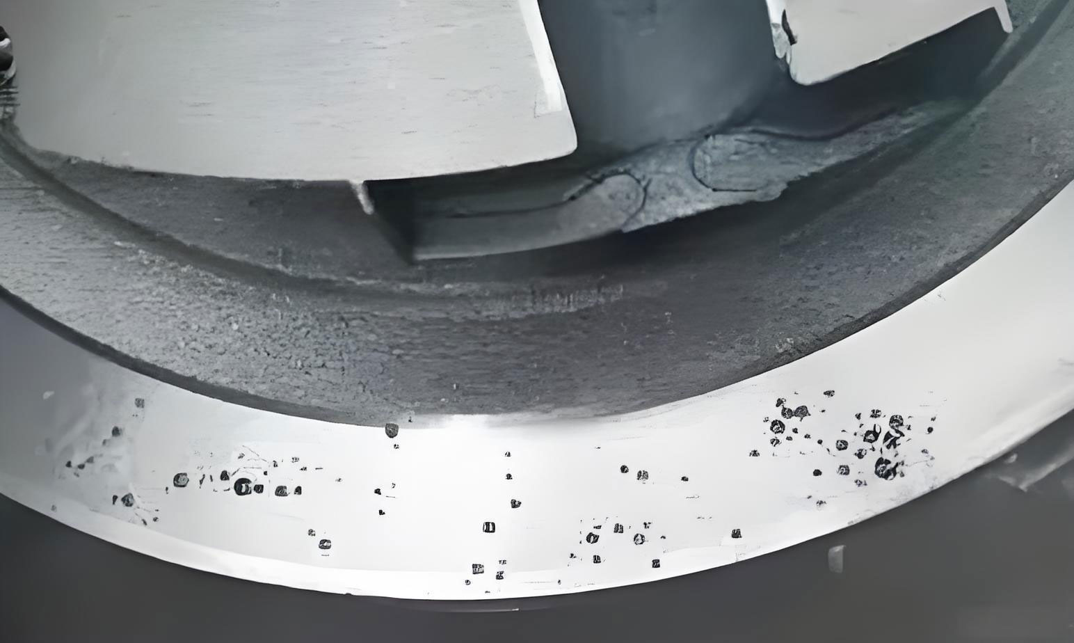
The morphology and location of the shrinkage in casting defects were highly consistent. They were clustered around the junctions of the three-row blind holes (shift fork shaft bores) with the main partition wall and in the cylinder bore section. These areas represented significant thermal masses or “hot spots.” In these regions, the wall thickness increased substantially from the nominal 7 mm to over 25 mm, creating isolated pools of metal that cooled and solidified later than the surrounding thinner sections. Once the adjacent thinner walls and the initial feeding channels solidified, these hot spots continued to contract in isolation, leading to internal shrinkage in casting defects due to the lack of liquid metal replenishment.
A detailed analysis of the contributing factors to this shrinkage in casting problem was conducted, considering the unique aspects of EPC and the component’s design:
1. Gating System Design and Pouring Parameters: The initial gating system featured a downsprue, horizontal runner, and ingates located at the central hole of the partition wall. The cross-sectional area decreased from the downsprue to the ingate. However, analysis suggested this design had insufficient feeding capacity. The ingates were likely solidifying before the critical hot spots, severing the vital feeding path prematurely. Pouring parameters also played a role. While a higher pouring temperature (e.g., 750-760°C) improves fluidity, it increases the liquid contraction $V_{liquid}$, potentially worsening the overall shrinkage in casting demand. Conversely, a lower temperature reduces fluidity and the thermal gradient needed for directional solidification towards the feeder. Pouring speed needed optimization; too fast could lead to turbulent filling and air entrapment, while too slow could cause premature chilling in thin sections, blocking feeding paths to thicker areas.
2. Component Geometry: The part’s design inherently promoted shrinkage in casting. The sudden change in wall thickness around the three-row holes and cylinder created isolated thermal centers. The aluminum melt, arriving through thinner sections, would lose superheat. Upon reaching these thick sections, it would accumulate heat, slowing down the cooling rate compared to the rapidly solidifying surrounding areas. Furthermore, the part’s significant height (464.3 mm) and long flow length (up to 664 mm from the pouring cup to the bottom) in an EPC environment exacerbated the challenge, as the foam decomposition and dry sand mold have different heat transfer characteristics compared to green sand, affecting the solidification sequence.
3. Mold Cooling Capacity: In EPC, the cooling rate is influenced by the unbonded sand’s properties and temperature. The sand’s heat capacity and conductivity determine its ability to extract heat. For a given sand, a lower initial sand temperature increases the cooling rate of the casting. Managing the sand temperature and its heat extraction potential is another lever to control the solidification gradient and mitigate shrinkage in casting.
To solve the problem of shrinkage in casting, a methodical approach combining numerical simulation and physical trial was employed. The core strategy was to redesign the gating system to enhance its feeding capacity, specifically by ensuring the ingates remained liquid longer than the problematic hot spots. This involved modifying the ingate configuration and introducing a key feature: a gate well (or pour cup/sprue base) at the bottom of the downsprue. The gate well acts as a reservoir of hot metal, helping to maintain thermal mass in the sprue and delaying its solidification, thereby extending the feeding time. Four distinct gating schemes were designed and analyzed using MAGMAsoft simulation software to predict the formation of shrinkage in casting.
| Scheme | Ingate Configuration at Central Hole | Key Design Feature | Simulation Prediction for Shrinkage Risk |
|---|---|---|---|
| Scheme I | Full circular ring, tapering from 25mm to 15mm width. | Single, continuous ingate perimeter. | Low risk in three-row hole area, but difficult to remove via machining. |
| Scheme II | Cross-shaped, four ingates (40mm wide each), tapering from 25mm to 15mm thick. One ingate aligned with the central boss of the three-row holes. | Directed feeding towards the critical hot spot. | Moderate risk, but better than initial design. |
| Scheme III | Cross-shaped, similar to II, but the ingate is rotated 45° relative to the three-row hole boss. | Less direct feed path to the critical area. | Higher predicted risk than Scheme II. |
| Scheme IV | T-shaped, three ingates (one removed opposite the critical area). | Reduced direct feeding to one quadrant. | Highest predicted risk for shrinkage in casting in the three-row hole region. |
Based on the simulation results, Scheme II was selected for physical trials as it offered a good balance between predicted feeding performance and practical manufacturability (ease of cutoff). A gate well of 80 mm in diameter and 40 mm in height was incorporated into all trial schemes. However, recognizing that ingate thickness is a critical variable controlling its solidification time and thus feeding capacity, further investigation was warranted. The solidification time $t_s$ of a section can be approximated by Chvorinov’s rule:
$$t_s = k \left( \frac{V}{A} \right)^n$$
Where $V$ is volume, $A$ is surface area, $k$ is a mold constant, and $n$ is an exponent (typically ~2). For an ingate, a larger $V/A$ ratio (i.e., greater thickness) leads to a longer solidification time $t_s$, extending its feeding duration. Therefore, the thickness of the ingates in Scheme II was varied to empirically determine the optimal dimension to prevent shrinkage in casting.
| Trial Batch | Ingate Thickness (Tapered from 25mm to final thickness) | Gate Well Dimensions | Number of Castings Poured | Non-Destructive Test (NDT) Results | Conclusion on Shrinkage in Casting |
|---|---|---|---|---|---|
| 1 | 12 mm | φ80 mm x 40 mm H | 6 | 3 out of 6 showed shrinkage porosity in three-row hole area. | Insufficient feeding capacity. Ingates solidified too early. |
| 2 | 15 mm | φ80 mm x 40 mm H | Over 300 (across multiple batches) | Zero defects detected in critical areas. | Optimal. Feeding duration matched solidification needs of hot spots. |
| 3 | 20 mm | φ80 mm x 40 mm H | 6 | 2 out of 6 showed shrinkage porosity. | Counterproductive. Possibly caused slower overall cooling or disturbed thermal gradient. |
The experimental results were decisive. The ingate thickness of 15 mm proved to be the optimal configuration. This dimension provided the precise balance needed to delay the solidification of the feeding channels long enough to compensate for the liquid and solidification contraction in the thermal centers, thereby eliminating shrinkage in casting. The success was validated over a production run exceeding 300 castings. The 12 mm ingates were too thin, solidifying prematurely and replicating the original shrinkage in casting problem. Interestingly, the 20 mm thick ingates also resulted in defects. This can be theorized using the concept of the “feeding zone.” An excessively large ingate can itself become a significant thermal mass, potentially creating a new, late-solidifying hot spot that requires feeding from elsewhere. It might also alter the intended solidification gradient, causing the critical section of the casting to solidify before the ingate itself is fully ready to feed it, or it may reduce the cooling rate of the entire local area, promoting a more pasty, mushy solidification mode prone to dispersed micro-shrinkage in casting.
The gate well played a crucial supporting role. By acting as a hot metal reservoir, it helped maintain the thermal gradient from the casting back to the sprue, supporting the concept of directional solidification. The combined effect of the correctly sized ingates and the gate well ensured that the path for liquid metal feed remained open until the moment the last part of the casting hot spot solidified. The relationship between ingate solidification time ($t_{gate}$) and hot spot solidification time ($t_{hotspot}$) is critical: to prevent shrinkage in casting, the condition $t_{gate} \geq t_{hotspot}$ must be satisfied. Our optimized design achieved this.
Furthermore, the principles derived from this study have broader applicability. The chemical solution used for the dissolution of copper contaminant layers was also tested for stripping electroplated nickel from reject parts. Operating at a warmed temperature of 40-60°C with air agitation, the stripping rate nearly doubled compared to room temperature operations. This demonstrates how process optimization for one aspect (defect remediation) can inform improvements in another (rework operations). The waste treatment for the spent stripping solution follows conventional neutralization and precipitation protocols, ensuring environmental compliance.
In conclusion, the resolution of shrinkage in casting defects in the aluminum alloy clutch housing was achieved through a systematic engineering approach. Key to this success was the understanding that defect prevention is not merely about adding more metal but about precisely controlling the solidification sequence and feeding dynamics. The integration of simulation software provided valuable insights for screening design options, but final validation through controlled physical trials was essential. The optimal solution comprised a cross-shaped ingate configuration with a final thickness of 15 mm, combined with an 80 mm x 40 mm gate well. This configuration maximized the feeding capacity of the gating system, ensuring it remained functional throughout the critical solidification period of the part’s thermal centers. This case underscores that in combating shrinkage in casting, particularly in complex EPC geometries, a nuanced understanding of thermal geometry, gating design, and their interaction is more effective than simplistic scaling of dimensions. The methodology of combining virtual prototyping with empirical validation, focusing on the precise timing of solidification events, provides a robust framework for solving similar shrinkage in casting challenges in other aluminum castings.