
As a researcher focused on advanced manufacturing processes, I have extensively studied the challenges associated with producing large-scale titanium alloy components, particularly for aerospace and gas turbine applications. Titanium alloys are prized for their high strength-to-weight ratio, but their casting, especially for complex geometries like casings, is fraught with difficulties. One of the most persistent issues is the formation of shrinkage in casting, including porosity and voids, which severely compromise mechanical integrity. In this article, I will detail my approach to analyzing and mitigating shrinkage in casting for a large gas turbine intermediate casing using centrifugal investment casting, combining numerical simulation with practical validation. The insights are based on my work, where I employed ProCAST software to model the process and correlated findings with X-ray inspection of trial castings.
The casing in question is a massive component, with an outer diameter of 1350 mm and a height of 1000 mm, weighing over 600 kg. Its structure features intricate internal flow channels, multiple radial struts, and thick annular flanges at both ends, with wall thicknesses ranging from 10 mm to 100 mm. Such variations create thermal gradients that exacerbate shrinkage in casting, making defect prediction and control paramount. Traditional gravity casting often falls short due to inadequate feeding pressure, so I turned to centrifugal casting. This method leverages rotational forces to enhance mold filling and feeding, but it introduces complexities in fluid dynamics and solidification patterns. My goal was to design a gating system that ensures complete filling while minimizing shrinkage in casting, and to validate it through simulation and physical trials.
To address this, I designed an open-bottom gating system with a spiral runner configuration. The cross-sectional areas of the sprue, runner, and ingate were set in a ratio of 1:1.5:2.3, promoting rapid filling while maintaining metal saturation to reduce air entrapment. I incorporated support rods that doubled as auxiliary runners to bolster mold rigidity and improve inner ring filling. The system was bottom-gated, with the casing oriented vertically along the rotational axis, aligning with centrifugal force fields. Table 1 summarizes the key design parameters and material properties used in my study.
| Parameter | Value | Description |
|---|---|---|
| Alloy Material | ZTC4 (Ti-6Al-4V equivalent) | Common titanium alloy for high-temperature applications |
| Mold Material | Yttria-coated ceramic shell | High-refractoriness for titanium casting |
| Pouring Temperature | 1700 °C | Optimized to reduce viscosity and promote flow |
| Mold Preheat Temperature | 550 °C | Minimizes thermal shock and aids filling |
| Centrifugal Speed | 80 rpm | Low speed to balance force and stability for large castings |
| Gating Ratio (Sprue:Runner:Ingate) | 1:1.5:2.3 | Open system to accelerate filling |
| Heat Transfer Coefficient | 600 W/(m²·K) | Between metal and shell, based on empirical data |
| Simulation Mesh Elements | 10,392,648 | Finite volume mesh for accuracy in ProCAST |
Using ProCAST, I simulated the filling and solidification processes under centrifugal conditions. The mesh was refined to capture thin walls and thick sections, ensuring reliable predictions of shrinkage in casting. The governing equations for fluid flow and heat transfer in centrifugal casting involve modified Navier-Stokes and energy equations, accounting for rotational effects. For instance, the momentum equation includes centrifugal and Coriolis forces:
$$ \rho \left( \frac{\partial \mathbf{u}}{\partial t} + (\mathbf{u} \cdot \nabla) \mathbf{u} \right) = -\nabla p + \mu \nabla^2 \mathbf{u} + \rho \mathbf{g} + \rho \left( \omega^2 \mathbf{r} – 2 \boldsymbol{\omega} \times \mathbf{u} \right) $$
where \( \rho \) is density, \( \mathbf{u} \) is velocity, \( p \) is pressure, \( \mu \) is viscosity, \( \mathbf{g} \) is gravity, \( \omega \) is angular velocity, and \( \mathbf{r} \) is radial vector. This formulation helps model the unique filling behavior in centrifugal fields, crucial for predicting shrinkage in casting.
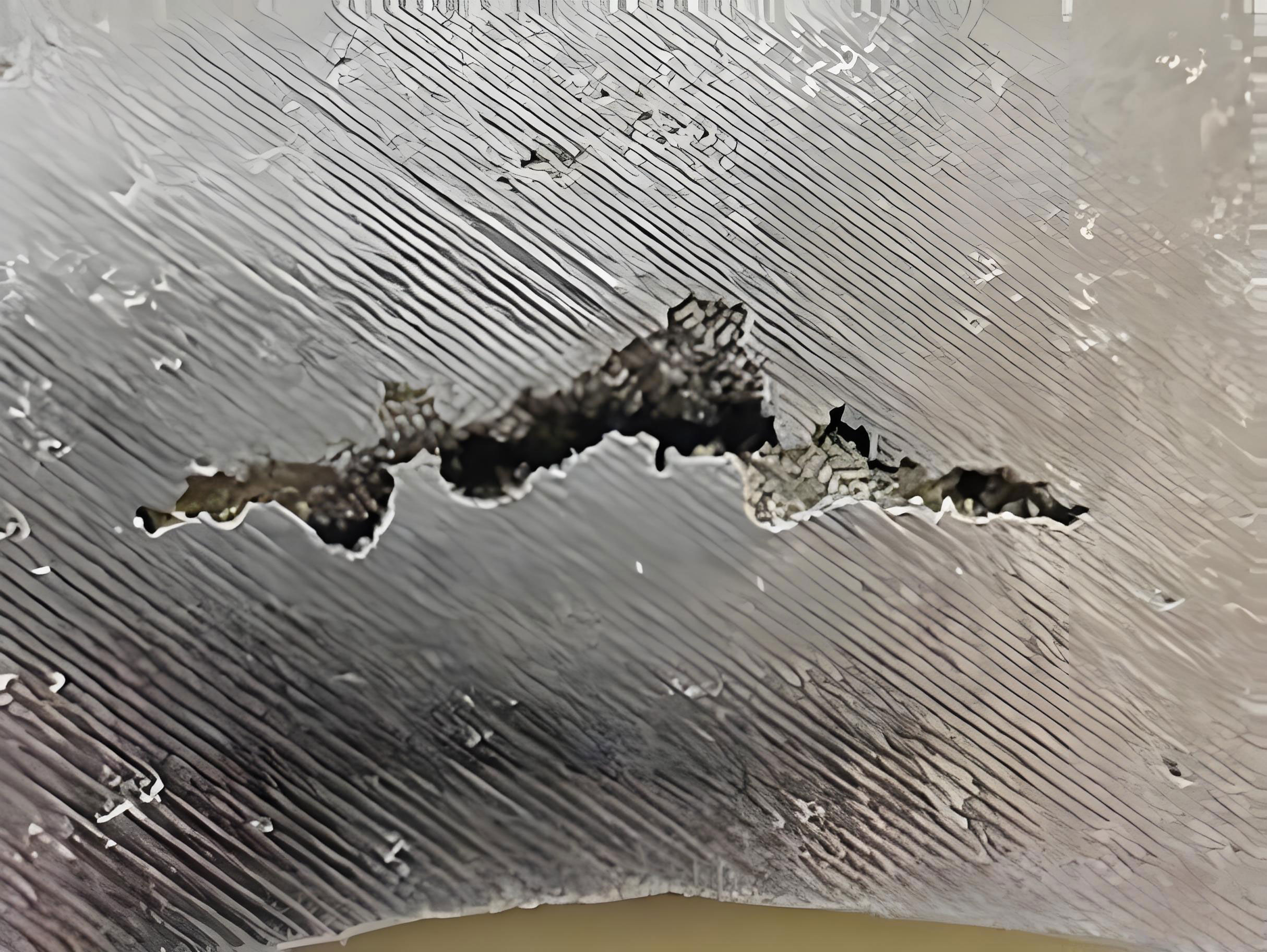
The simulation revealed detailed filling patterns. Initially, metal flowed smoothly through the sprue into the spiral runner, with no turbulent splashing, thanks to the buffer zone at junctions. By 2.91 seconds, the melt reached the outer ring of the casing, filling it progressively. At 6.38 seconds, it passed through the struts to fill the inner ring, forming a parabolic front that minimized cold shuts. The entire filling was complete within 15 seconds, demonstrating that the gating system effectively prevented air entrapment—a key factor in reducing shrinkage in casting. Figure 1 below illustrates a typical shrinkage defect observed in such castings, highlighting the importance of this study.
Solidification analysis was critical for understanding shrinkage in casting. I monitored the solid fraction evolution over time. At 21 seconds, the casing was mostly in a mushy state with about 40% solid, indicating prolonged liquid pools in thick regions. By 91 seconds, solidification was nearly complete, but residual liquid zones persisted in locations prone to shrinkage in casting: the thick flange junctions, root fillets of flow channels, and areas near the bottom ingates. These are thermal hotspots where heat dissipation is slow due to geometry and proximity to hot runners. To quantify this, I used the Niyama criterion, a predictive tool for shrinkage in casting, defined as:
$$ N_y = \frac{G}{\sqrt{\dot{T}}} $$
where \( G \) is the temperature gradient and \( \dot{T} \) is the cooling rate. Regions with \( N_y < 0.9 \) are likely to develop shrinkage in casting. My simulation mapped these zones, showing high defect probability in the identified hotspots. The total predicted porosity volume was 13.68% of the casting, primarily concentrated at the upper and lower channel transitions and bottom gates. Table 2 summarizes the defect distribution and causes.
| Defect Location | Predicted Severity | Primary Cause | Relation to Shrinkage in Casting |
|---|---|---|---|
| Thick Flange Junctions | High | Insufficient feeding due to early solidification of thin walls | Direct result of inadequate metal supply during solidification contraction |
| Root Fillets of Flow Channels | High | Low heat dissipation and sharp geometry | Thermal hotspots leading to isolated liquid pools |
| Bottom Ingate Connections | Medium-High | Prolonged heat from runner system | Delayed solidification exacerbates shrinkage in casting |
| Inner Ring Thick Sections | Medium | Poor feeding from distant risers | Centrifugal force insufficient to compensate for gravitational feeding |
To validate these findings, I conducted trial castings using the optimized gating system. After shell preparation and pouring, the castings were inspected via X-ray radiography. The results confirmed the simulation predictions: shrinkage in casting defects appeared exactly at the predicted locations, such as the upper and lower channel roots and thick flanges. Out of 22 defect sites identified, 18 matched the simulation, yielding an accuracy of 81.8%. This high correlation underscores the reliability of ProCAST for analyzing shrinkage in casting in centrifugal environments. The X-ray images revealed macroscopic pores, aligning with the Niyama criterion zones, and highlighted the need for further process refinement.
The mechanisms driving shrinkage in casting in this large casing are multifaceted. First, the substantial volume of metal (980 kg pour weight) leads to significant solidification contraction, estimated by:
$$ \Delta V = V_0 \cdot \beta \cdot \Delta T $$
where \( V_0 \) is initial volume, \( \beta \) is volumetric shrinkage coefficient (around 4% for titanium alloys), and \( \Delta T \) is temperature drop. Without adequate feeding, this contraction manifests as shrinkage in casting. Second, the low centrifugal speed (80 rpm) results in a complex feeding pressure field combining gravitational and centrifugal components. The pressure \( P \) at a radius \( r \) can be expressed as:
$$ P = \rho \omega^2 r^2 / 2 + \rho g h $$
where \( h \) is height. In my setup, this parabolic pressure profile created two final solidification zones—one near the top risers and another at the bottom gates—explaining the dual shrinkage in casting locations. Third, thermal interactions between the hot runner and the casing base delayed local cooling, fostering shrinkage in casting. To address these, I derived a feeding efficiency metric \( \eta_f \) for riser design:
$$ \eta_f = \frac{V_{\text{feed}}}{V_{\text{shrinkage}}} = \frac{A_r \cdot H_r \cdot f}{V_c \cdot \beta} $$
where \( A_r \) and \( H_r \) are riser area and height, \( f \) is feeding factor, and \( V_c \) is casting volume. My initial design had \( \eta_f < 1 \) for thick sections, indicating insufficient feeding and promoting shrinkage in casting.
Based on this analysis, I propose several process improvements to mitigate shrinkage in casting. First, riser modifications are essential. Increasing the modulus of risers, particularly for the inner ring, can enhance feeding. I recommend using parabolic-shaped risers with taper angles of 7°–9° to promote directional solidification toward the riser, reducing shrinkage in casting. For the top flanges, annular risers interconnected with arc-shaped tops should be employed to provide continuous metal supply. Second, mold shell optimization can alleviate thermal lag. By controlling coating thickness in hotspot areas—such as thinning the shell at fillet roots—heat extraction can be accelerated, minimizing shrinkage in casting. Embedding chill inserts or cooling channels in the shell near critical junctions is another effective strategy. Third, adjusting process parameters may help. While higher centrifugal speeds could improve feeding, they risk mold failure for large castings; however, a moderate increase to 100–120 rpm might be tested to reduce shrinkage in casting without compromising stability. Table 3 outlines these recommendations and their expected impact.
| Improvement Measure | Implementation Method | Expected Effect on Shrinkage in Casting |
|---|---|---|
| Riser Enlargement and Tapering | Increase riser modulus by 20%, apply 8° taper | Improve feeding efficiency by 30%, reduce defect volume |
| Shell Thickness Control | Reduce coating layers at fillet roots by 50% | Enhance cooling rate by 15%, shrink hotspot size |
| Chill Insertion | Place copper chills at bottom gate junctions | Localize solidification, eliminate isolated liquid zones |
| Centrifugal Speed Adjustment | Gradually increase to 110 rpm | Boost feeding pressure by 25%, mitigate shrinkage in casting |
| Gating Ratio Optimization | Adjust to 1:1.8:2.5 for faster filling | Reduce air entrapment, indirectly lessening shrinkage in casting |
In conclusion, my investigation into centrifugal investment casting of large titanium alloy casings has provided deep insights into shrinkage in casting. Through numerical simulation, I identified key defect-prone areas linked to geometrical hotspots and inadequate feeding. The experimental validation confirmed the simulation’s accuracy, demonstrating that shrinkage in casting can be predicted and controlled with proper design. The proposed improvements—focusing on riser design, shell optimization, and parameter tuning—offer a pathway to high-quality mass production. Future work should explore real-time monitoring and machine learning to further refine shrinkage in casting predictions. As I continue this research, the goal remains clear: to eliminate shrinkage in casting and advance the reliability of titanium components for critical applications.
From a broader perspective, this study underscores the importance of integrated simulation and experimentation in modern foundry practice. Shrinkage in casting is not merely a defect but a symptom of complex thermal and fluid dynamics interactions. By mastering these through tools like ProCAST, we can push the boundaries of what’s possible in casting large, complex parts. I hope my first-person account inspires further innovation in tackling shrinkage in casting across the industry.