
Abstract
The typical defects encountered in the production of steel castings for valve housings, specifically addressing the issue of core floating. By analyzing the root causes of instability in the molding process and insufficient stiffness of the core bone, a novel design approach featuring a double-row core bone is introduced. Through the integration of various measures such as core head fixation, box closing and checking, and reverse deformation compensation, the problem of core floating in valve housing steel castings is effectively tackled, leading to improved product quality and reduced reject rates.
1. Introduction
Valve housing steel castings, as pressure vessels operating under high temperatures and intensities, are typically formed through casting processes. These castings can be classified into thick-walled and thin-walled types based on the ratio of their outer diameter to inner diameter. During the pouring process, the buoyancy exerted by the molten steel on the sand core can be four to five times the core’s weight, significantly impacting its positioning. This often results in uneven wall thicknesses, dimensional deviations, and even casting scrap due to excessive deviations. This phenomenon, known as core floating, can also lead to defects such as porosity. Therefore, controlling core floating is crucial in the production of valve housing steel castings.
2. Formation and Typical Defects of Steel Castings for Valve Housings
2.1 Formation Method
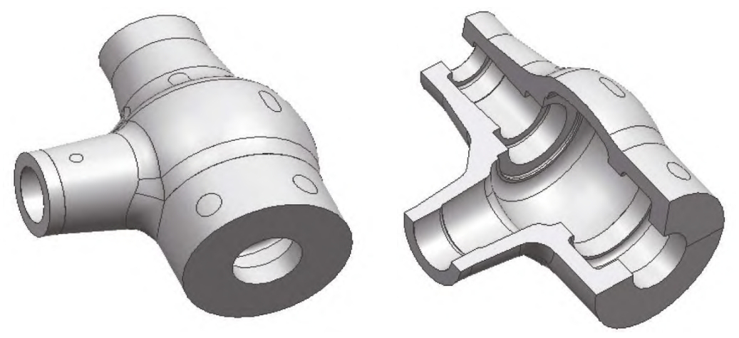
Taking the production process of a large main steam valve housing casting as an example, this casting features a contour size of 2,990 mm × 2,200 mm × 1,550 mm and a mass of approximately 18 tons. It has a “T”-shaped hollow structure with a minimum wall thickness of 100 mm, classifying it as a thin-walled valve housing. The casting is produced using a two-box molding method to facilitate sand core support and feeding, with the internal cavity formed by the sand core.
2.2 Typical Defects
The typical defects observed in these castings are dimensional deviations and porosity. Dimensional deviations mainly manifest in the internal cavity, with the external dimensions remaining within specifications. Spherical wall thickness measurements reveal that the upper section of the casting has thinner walls, while the lower section has thicker walls, indicating core floating during pouring. Additionally, porosity defects have been detected in some castings, which deviate from computer simulation results. Analysis shows that these porosity defects are related to core floating, which alters the feeding channels.
Table 1: Dimensional Analysis of Spherical Wall Thickness of Castings
| Casting | Sand Core Span (L) | Core Bone Diameter | Theoretical Wall Thickness | Actual Casting Wall Thickness Measurements (mm) | Core Floating Amount (mm) |
|---|---|---|---|---|---|
| Valve Shell 1 | 2,700 | 100 | 90 | 75, 81, 90, 98, 105, 97 | 8-23 |
| Valve Shell 2 | 2,700 | 100 | 90 | 73, 80, 89, 99, 107, 98 | 11-27 |
| Valve Shell 3 | 2,700 | 100 | 90 | 74, 81, 91, 97, 106, 97 | 8-23 |
| Valve Shell 4 | 3,590 | 120 | 100 | 77, 87, 91, 101, 122, 110 | 8-23 |
| Valve Shell 5 | 3,590 | 120 | 100 | 80, 89, 100, 110, 120, 109 | 8-20 |
| Valve Shell 6 | 3,590 | 120 | 100 | 79, 88, 100, 111, 121, 110 | 8-21 |
3. Improvement Measures
3.1 Core Bone Design Improvement
The original core bone used single-row welding of φ100-120 mm round steel with a span of approximately 3,300 mm. Due to its simple structure and insufficient stiffness, there was a risk of core floating. Increasing the diameter of the round steel would significantly raise costs and still pose a risk of core floating. Therefore, the core bone structure was modified from a single-row to a double-row design to increase its cross-sectional area and stiffness. To save costs, cut straight pouring bars were used instead of round steel.
3.2 Core Head Fixation
To ensure the stability of the sand core during the molding process, the core heads were fixed to the lower box sand mold. Specific methods include pre-embedding core head markers in the lower box sand mold during molding and welding additional markers on the core heads of the double-row core bone. These markers were then welded together after placing the sand core to enhance stability.
3.3 Core Head Gap Inspection
Due to factors such as sand core compaction and deformation during lifting, there may be gaps at the core heads after placing the sand core, which cannot be directly detected after box closing. Mud strips were laid on each sand core’s core head to confirm the gap between the upper mold and the sand core. The compaction of the mud strips after box closing was used to judge whether the gap exceeded the specified limit.
3.4 Reverse Deformation Compensation
To mitigate the risks of core floating due to mold deformation, core head gaps, and pouring buoyancy, reverse deformation compensation was applied to the inner cavity of the casting. The upper section of the core box was adjusted to the upper limit of the standard tolerance to compensate for the core floating amount.
4. Effectiveness Verification
After implementing the above improvements, measurements showed that the dimensional deviation due to core floating was reduced to 1-3 mm, and the porosity volume was decreased to 0.3-0.5 dm³, both meeting customer tolerance requirements. Compared to previous castings, the dimensional deformation control was significantly improved, with the welding repair rate (cubic decimeters per ton of casting) reduced from 1.64 dm³/t to 0.24 dm³/t.
Table 2: Comparison of Casting Quality Before and After Improvements
| Item | Before Improvement | After Improvement |
|---|---|---|
| Dimensional Deviation Due to Core Floating (mm) | 10-25 | 1-3 |
| Porosity Volume (dm³) | 2.5-3 | 0.3-0.5 |
| Welding Repair Rate (dm³/t) | 1.64 | 0.24 |
5. Conclusion
This study introduces a double-row core bone design that improves stiffness by 1-2 times compared to the single-row design. Using straight pouring bars instead of round steel reduces costs. Additionally, sand core markers and mud strip inspections ensure the stability of the sand core after placement. By following standardized operating procedures and documenting inspection issues, future improvements and analyses are facilitated.
The implementation of the double-row core bone design effectively controls the problem of core floating. Compared to traditional methods, the dimensional deviation due to core floating has been reduced from 10-25 mm to 1-3 mm, within the tolerance range. Furthermore, porosity defects caused by core floating have been improved, significantly reducing the number of repairs, saving costs, and shortening the production cycle.