
Abstract
The typical defects encountered in steel valve casing castings, particularly focusing on the issue of core floating. By analyzing the root causes of instability during the molding process and insufficient stiffness of the core bone, a novel design approach featuring a double-row core bone is introduced. Through the integration of various measures such as core head fixation, box closing and checking procedures, and the application of reverse deformation, the problem of core floating in valve casing castings is effectively addressed. These improvements lead to significant enhancements in product quality and yield.
1. Introduction
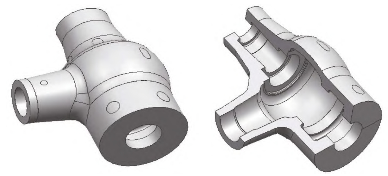
Steel valve casings, as pressure vessels operating under high temperatures and intensities, are typically formed through casting processes. Depending on the ratio of the outer diameter to the inner diameter (K), valve casings can be classified as thin-walled or thick-walled. When K ranges between 1.1 and 1.2, it is considered a thin-walled valve casing; otherwise, it is classified as thick-walled. The hollow cavity is formed by sand cores, with core heads located at both ends of the tube opening.
During the pouring process, the buoyancy force exerted by the molten steel on the sand core is approximately 4 to 5 times the weight of the sand core. This significant buoyancy has a considerable impact on the positioning of the sand core, often leading to uneven wall thicknesses in the upper and lower parts of the casting, causing dimensional deviations and even scrap due to excessive deviations. This phenomenon, known as core floating, results in defects such as dimensional deviations and porosity in the castings. Therefore, controlling core floating is crucial in the production of valve casing steel castings.
2. Formation and Typical Defects of Steel Valve Casing Castings
2.1 Formation Method
Taking the production process of a large-scale main steam valve casing casting as an example, this section illustrates the typical formation method. The casting has contour dimensions of 2,990 mm × 2,200 mm × 1,550 mm and a mass of approximately 18 tons. It features a “T”-shaped hollow structure with a minimum wall thickness of 100 mm, classifying it as a thin-walled valve casing.
To facilitate sand core support and feeding of the casting, the molding method adopts a horizontal position, with the casting process typically designed as two-box molding. The internal cavity is formed by a sand core, which is positioned and secured through core heads with the upper and lower molds to form the mold cavity.
2.2 Typical Defects
The typical defects observed in these castings are dimensional deviations and porosity. Dimensional deviations mainly manifest in the internal cavity, with the external dimensions remaining within specifications. Spherical wall thickness measurements reveal that the wall thickness in the upper part of the mold is smaller by 10 to 23 mm, while the wall thickness in the lower part is larger by the same amount, indicating that the sand core shifts upwards during pouring, leading to size deviations, i.e., core floating.
Moreover, porosity defects are found in some castings upon non-destructive testing (NDT), which deviate from computer simulation results. Analysis shows that these porosity defects are related to core floating, which alters the feeding channels, resulting in porosity.
3. Improvement Measures
3.1 Core Bone Design Improvement
The original core bone used φ100 to φ120 mm round steel in a single-row welding configuration, with a span of approximately 3,300 mm. However, due to its simple structure and insufficient stiffness, there is a risk of core floating. Increasing the diameter of the round steel would significantly raise costs and still pose a risk of core floating.
Therefore, a new design featuring a double-row core bone is introduced. This design increases the cross-sectional area of the core bone by transitioning from a single-layer to a double-layer structure to enhance stiffness. To reduce costs, cut straight gating rods can be used instead of round steel. The double-row core bone consists of upper and lower parallel trunks, as well as reinforcing rods. The trunks are welded into a “T”-shaped structure using φ100 to φ120 mm straight gating rods. Two trunks are connected by several reinforcing rods (φ20 to φ30 mm in diameter, 120 to 150 mm in length) spaced 500 to 600 mm apart. Additional reinforcing rods (60 to 80 mm square steel) are welded to increase stability.
Table 1: Comparison of Original and Improved Core Bone Designs
| Design Feature | Original Core Bone | Improved Double-Row Core Bone |
|---|---|---|
| Material | φ100 to φ120 mm round steel | φ100 to φ120 mm straight gating rods |
| Structure | Single-row welding | Double-row with reinforcing rods |
| Span | ~3,300 mm | ~3,300 mm (maintained) |
| Stiffness | Low, risk of core floating | High, reduced risk of core floating |
3.2 Core Head Fixation
To ensure the stability of the sand core during the molding process, the core heads are fixed to the lower mold sand. Specifically, core head markers are pre-embedded in the lower mold sand and welded to the core heads of the double-row core bone. These markers are made of 60 to 80 mm square steel, with precise length dimensions to ensure a secure fit.
3.3 Core Head Gap Inspection
Due to factors such as compaction and deformation during lifting, there may be gaps between the core heads after they are placed. To detect these gaps, mud strips are laid on each core head before closing the upper mold. The diameter of the mud strips is controlled at φ8 to φ10 mm. After closing and then lifting the upper mold, the compaction degree of the mud strips at the core heads indicates the gap size. If the mud strips are compressed to a thickness of 1 to 3 mm, the gap is within specifications. If the thickness exceeds 3 mm, further verification and adjustments are required.
Table 2: Core Head Gap Inspection Criteria
| Inspection Criterion | Description |
|---|---|
| Mud Strip Diameter | φ8 to φ10 mm |
| Acceptable Gap | 1 to 3 mm (compressed mud strip) |
| Action Required | Further verification and adjustment if >3 mm |
3.4 Reverse Deformation
To mitigate the risks of deformation, core head gaps, and pouring buoyancy, reverse deformation compensation is applied. The inner cavity of the casting is adjusted to the upper limit of the standard tolerance on the core box’s upper part to compensate for potential core floating.
4. Effectiveness Verification
After implementing the above improvements, measurements show that the dimensional deviation due to core floating is reduced to 1 to 3 mm, and the porosity volume is decreased to 0.3 to 0.5 dm³, both meeting customer tolerance requirements. Compared to previous castings, the dimensional deformation control is significantly improved, with the welding repair rate (cubic decimeters per ton of casting) reduced from 1.64 dm³/t to 0.24 dm³/t.
Table 3: Comparison of Casting Quality Before and After Improvements
| Quality Indicator | Before Improvement | After Improvement |
|---|---|---|
| Dimensional Deviation (mm) | 10 to 25 | 1 to 3 |
| Porosity Volume (dm³) | 2.5 to 3 | 0.3 to 0.5 |
| Welding Repair Rate (dm³/t) | 1.64 | 0.24 |
5. Conclusion
This study introduces a double-row core bone design, which enhances stiffness by 1 to 2 times compared to the single-row design. Using straight gating rods instead of round steel reduces costs. Additionally, core head markers and mud strip inspection measures ensure the stability of the sand core after placement. These improvements effectively control the core floating issue, reducing dimensional deviations from 10 to 25 mm to within the tolerance range of 1 to 3 mm. Furthermore, porosity defects caused by core floating are improved, significantly reducing repair work, saving costs, and shortening the production cycle.