
In our extensive experience with casting critical components, the production of large hollow ductile iron crankshafts presented a significant technological hurdle. These crankshafts, essential for heavy-duty compressors, demand exceptional mechanical properties, precise geometry, and a high-quality surface finish. To meet these stringent requirements, we adopted the sand coated iron mold casting process, known for its ability to produce dense, dimensionally accurate castings with refined microstructures due to its rapid cooling characteristics. However, initial attempts yielded castings with internal shrinkage porosity, leading to high rejection rates. This narrative details our journey in overcoming these challenges by fundamentally applying the proportional solidification theory, a guiding principle that revolutionized our approach to gating, risering, and metallurgical control in sand coated iron mold casting.
The specific component in focus was a large, fully hollow crankshaft with four throws arranged at 180 degrees. The overall length measured 2880 mm, with main journal diameters of 200 mm and an internal hollow core of 110 mm, resulting in a nominal wall thickness of 45-50 mm. The casting weight was approximately 700 kg. The material specification was QT600-3 ductile iron, requiring a pearlitic matrix in the as-cast condition to achieve tensile strength over 600 MPa and elongation around 3%. The complexity lay not only in its size and hollow structure but also in the necessity to avoid post-casting heat treatment to prevent dimensional distortion, making the achievement of a sound, as-cast pearlitic structure paramount.
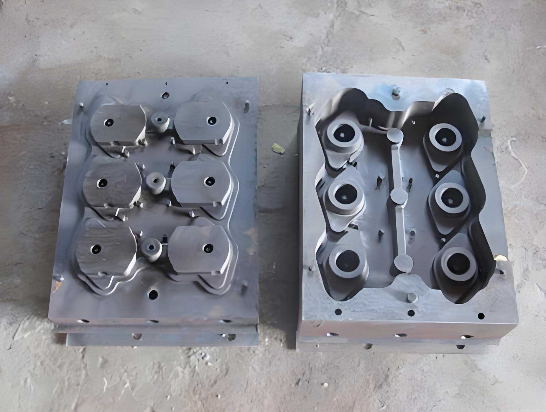
Our initial process for sand coated iron mold casting was designed around the principle of simultaneous solidification. The rationale was to leverage the high cooling rate and mold rigidity of the sand coated iron mold to maximize the use of graphite expansion for internal feeding, thereby eliminating the need for large risers. The process employed a horizontal molding, horizontal pouring, and horizontal solidification sequence. The sand coating thickness on the iron mold was set at 10 mm, with the iron mold body itself being 30 mm thick—three times the coating thickness to ensure sufficient thermal mass and rigidity. The gating system was open and of the stopper-pour type. The chemical composition initially used is summarized in Table 1.
| Element | C | Si | Mn | P | S | ∑RE | Mgres |
|---|---|---|---|---|---|---|---|
| Content | 3.6-3.9 | 2.0-2.6 | 0.5-0.8 | <0.10 | <0.03 | 0.02-0.05 | 0.03-0.06 |
Venting was provided only via small 16 mm diameter vents at the highest points of each throw. This initial sand coated iron mold casting process was executed, but upon final machining, severe shrinkage porosity was discovered in the upper sections of the crankpins, as illustrated conceptually in a specific location. All initial castings were scrapped. Furthermore, attempts at high-temperature annealing to dissolve carbides resulted in unacceptable plastic creep, elongating the shaft by 6-8 mm. This dual failure underscored the inadequacy of a simple simultaneous solidification approach for this application in sand coated iron mold casting.
A rigorous analysis was conducted, rooted in the principles of proportional solidification theory. This theory posits that the self-feeding capability of cast iron arises from the dynamic, time-dependent balance between liquid contraction and graphite expansion during solidification, not merely the algebraic sum of total shrinkage and expansion. Crucially, liquid contraction occurs early in the solidification sequence, while the expansive force from graphite precipitation happens later. The sequence can be represented conceptually by a contraction-expansion curve. For ductile iron, the relevant volumetric changes can be quantified. The liquid contraction (SL) from pouring temperature (Tp) to the eutectic temperature is given by:
$$ S_L = \alpha_L \times \frac{(T_p – T_{eutectic})}{100} $$
Where $\alpha_L$ is the liquid contraction coefficient, typically around 1.5%/100°C for ductile iron. For a Tp of 1350°C and Teutectic of approximately 1150°C, this yields $S_L \approx 3\%$.
The contraction due to austenite formation during the eutectic reaction (Sr) and the expansion from graphite precipitation (Ege) are more complex functions of composition. They can be estimated using formulas that consider carbon equivalents (CE), actual carbon content (Cx), and solubility limits. A simplified representation is:
$$ S_r = f(C_x, CE) \times \beta_{Au} $$
$$ E_{ge} = f(C_x, CE) \times \beta_{Gr} $$
Where $\beta_{Au}$ and $\beta_{Gr}$ are the specific volumetric change coefficients for austenite contraction and graphite expansion, respectively. Using standard values and our initial composition (Cx=3.6, Si=2.5, CE≈3.44), calculations showed Ege – SL – Sr yielded a small positive net expansion under idealized equilibrium conditions. However, the sand coated iron mold casting environment dramatically alters this balance. The high cooling rate accelerates and concentrates the liquid contraction phase, while the graphite expansion is delayed and may be partially suppressed if the cooling is too rapid to allow complete graphitization. The stiffness of the sand coated iron mold, while beneficial for containing expansion, cannot compensate for the early liquid contraction if no liquid feed path is available. The small vents solidified almost instantly, providing no feeding capability. This mismatch, where early contraction demand exceeded the later available expansion, was the root cause of the shrinkage porosity. Metallographic examination of the failed castings confirmed the presence of cementite, which further hindered graphite expansion and validated the theory.
Guided by proportional solidification and the concept of finite feeding, we completely redesigned the sand coated iron mold casting process. The core insight was to provide a controlled source of liquid metal to compensate for the initial liquid contraction before the graphite expansion becomes active. This was achieved by converting the two small vents on the highest throw into open risers. The riser design was critical; it was sized as a “neutral thermal node” riser according to proportional solidification principles—large enough to remain liquid longer than the adjacent casting section to feed the contraction, but not excessively large to waste metal or create new hot spots. The revised sand coated iron mold casting layout implemented this change.
Concurrently, we overhauled the metallurgical approach to maximize and timely promote graphite expansion while achieving a pearlitic matrix without heat treatment. The goal was to enhance the “self-feeding” capacity within the sand coated iron mold. The chemical composition was strategically modified, as detailed in Table 2.
| Element | C | Si | Mn | P | S | Cu | Sn | ∑RE | Mgres |
|---|---|---|---|---|---|---|---|---|---|
| Target | 3.6-3.8 | 2.2-2.6 | ≤0.6 | <0.07 | <0.03 | 0.4 | 0.03 | 0.02-0.04 | 0.03-0.05 |
The rationale was as follows: Carbon and silicon were balanced to a higher carbon equivalent (CE ≈ 4.4-4.5%) to improve graphitization potential. Manganese was limited to avoid carbide stabilization. The key was the synergistic addition of copper (0.4%) and tin (0.03%). Copper refines graphite and pearlite, enhancing strength. Tin is a powerful pearlite stabilizer that does not promote massive carbides. Their combined action reliably yields over 70% pearlite in the as-cast state within the rapid cooling sand coated iron mold casting environment. The foundation for this can be linked to the effect on the solidification path and phase transformation kinetics, which can be modeled using concepts like the pearlite-forming factor (Pf):
$$ P_f = k_{Cu} \cdot [\%Cu] + k_{Sn} \cdot [\%Sn] + … $$
Where kCu and kSn are potency coefficients. For our targets, Pf ensures a pearlitic transformation upon cooling.
To counteract the chilling tendency of the sand coated iron mold and the graphitization-inhibiting effect of magnesium, we implemented a robust, multi-stage inoculation practice. The sequence is summarized in Table 3.
| Stage | Location | Inoculant (FeSi75) | Amount (wt.%) | Particle Size | Purpose |
|---|---|---|---|---|---|
| 1 | In-mold (with nodulizer) | Regular | 0.5 | 10-15 mm | Primary graphitization |
| 2 | Pouring stream (trough) | Regular | 0.3 | 10-15 mm | Delayed inoculation |
| 3 | Pouring lip (stream) | Powder | 0.15 | 50-70 mesh | Instant, late inoculation |
The total inoculation addition was nearly 1%. This practice ensured a high nodule count, suppressed carbides, and promoted a uniform, fine graphite structure essential for effective expansion. The pouring temperature was controlled between 1340-1360°C, with a pouring time of 50-60 seconds, followed by a mold cooling time of 12-14 hours in the sand coated iron mold.
The implementation of this integrated approach—proportional riser design, optimized alloying, and intensive inoculation—within the sand coated iron mold casting framework was thoroughly validated. A batch of crankshafts was produced. Non-destructive testing via ultrasound and magnetic particle inspection revealed no shrinkage defects. Tensile testing and metallographic analysis on samples taken from the castings confirmed the success. The results are consolidated in Table 4.
| Sample ID | Nodularity Grade | Pearlite (%) | Ferrite (%) | Carbide+Phosphide (%) | Tensile Strength (MPa) | Elongation (%) |
|---|---|---|---|---|---|---|
| 1 | 3 | 74 | 25 | 1.0 | 700 | 2.2 |
| 2 | 3 | 73 | 25 | 2.0 | 664 | 3.4 |
| 3 | 3 | 70 | 30 | 0.0 | 675 | 4.0 |
| 4 | 3 | 83.5 | 15 | 1.5 | 749 | 3.0 |
All properties met and exceeded the QT600-3 specification, achieving the goal of as-cast pearlitic ductile iron. The economic impact was substantial. Compared to the previous outsourced forged steel alternative, the sand coated iron mold casting process reduced the unit production cost by an order of magnitude, resulting in significant annual savings.
In conclusion, the successful production of large, hollow, high-performance ductile iron crankshafts hinges on a deep understanding and application of proportional solidification theory within the specific context of sand coated iron mold casting. The process is not merely about exploiting mold rigidity but involves a holistic design that addresses the time-phased nature of shrinkage and expansion. Key takeaways include: First, in sand coated iron mold casting for moderately thick-walled ductile iron castings, liquid contraction cannot be ignored; finite feeding via properly designed risers based on neutral thermal node principles is essential. Second, the metallurgy must be tailored to synergize with the process. The combination of Cu and Sn micro-alloying, coupled with a multi-stage, high-intensity inoculation strategy, is highly effective in achieving a sound, as-cast pearlitic matrix under rapid cooling conditions. This integrated approach transforms the sand coated iron mold from a mere rapid cooling tool into a controllable environment for producing superior castings. The principles established here have broad applicability for other complex, high-integrity castings manufactured via sand coated iron mold casting, demonstrating that theory-guided practice is indispensable for advancing foundry technology.