
In modern manufacturing, the lost wax investment casting process remains a critical method for producing complex, high-precision metal components, particularly in aerospace, automotive, and industrial applications. As an engineer specializing in mold design, I have leveraged CAD/CAM technologies to streamline the development of molds for connector parts, which are essential in various mechanical systems. This article details my first-person approach to designing a mold for a connector part using lost wax investment casting, focusing on the integration of Pro/Engineer software for modeling, simulation, and manufacturing. The goal is to demonstrate how CAD/CAM systems enhance efficiency, accuracy, and cost-effectiveness in mold production, with repeated emphasis on the lost wax investment casting technique to underscore its relevance throughout the design lifecycle.
My journey begins with a thorough analysis of the connector part, which features a cavity, side plates, an inclined cylindrical tube, and reinforcing ribs. In lost wax investment casting, the mold must accurately replicate these geometries to ensure the final wax pattern and subsequent metal casting meet stringent tolerances. Using Pro/Engineer, I created a 3D model of the part, starting with the cavity via rotational commands, followed by extruding the side plates and surface engravings. The inclined cylindrical tube posed a challenge due to its spatial orientation, requiring careful construction of axes and planes, while the reinforcing ribs demanded interpretation based on drawings and spatial imagination. This modeling phase is crucial, as any inaccuracies can propagate through the lost wax investment casting process, leading to defects in the final product. The completed solid model served as the reference for all subsequent mold design steps, ensuring fidelity to the original design intent.
With the part model finalized, I proceeded to the mold design phase, which is central to the lost wax investment casting workflow. In Pro/Engineer, I initiated a new mold file, imported the reference part, and created a blank workpiece to represent the mold base. A key consideration in lost wax investment casting is accounting for shrinkage during wax solidification and metal cooling; therefore, I applied a shrinkage factor of 0.008 based on empirical data from similar lost wax investment casting projects. This factor ensures the mold cavity is slightly enlarged to compensate for dimensional changes, as described by the formula: $$ D_{mold} = D_{part} \times (1 + S) $$ where \( D_{mold} \) is the mold dimension, \( D_{part} \) is the part dimension, and \( S \) is the shrinkage rate. For lost wax investment casting, such calculations are vital to achieving net-shape or near-net-shape castings.
The design of parting surfaces is a critical step in mold creation for lost wax investment casting. I defined the main parting plane along the central axis parallel to the front view, allowing mold opening in a direction perpendicular to this plane to avoid interference from the inclined features. Additionally, I created slider parting surfaces for the cylindrical tubes and reinforcing ribs, as shown in Figure 3 of the original context, to facilitate core extraction. These surfaces must completely intersect the mold volume without self-intersection, a requirement I verified using Pro/Engineer’s merging tools. The gating system was then designed to ensure proper wax flow during injection, which is essential for producing defect-free wax patterns in lost wax investment casting. I used volume splitting operations to generate separate mold components, including upper and lower mold halves, core sliders, and side sliders, all tailored for the lost wax investment casting process.
To ensure mold integrity during operation, I incorporated positioning and locking mechanisms. For the lost wax investment casting mold, I employed pin locators on the diagonal of the upper and lower molds, with cylindrical pins fitted via clearance and interference fits, respectively. Sliders were connected using tubular pins and screws for core pulling, while double-ended studs secured the mold halves. This design minimizes misalignment and wear, which is crucial in lost wax investment casting where repeated cycles can affect mold accuracy. I simulated the mold opening sequence in Pro/Engineer to validate the mechanism, generating an explosion view that confirmed smooth operation without collisions—a testament to the precision enabled by CAD in lost wax investment casting mold design.
The manufacturing phase for the lost wax investment casting mold involved detailed process planning. I selected an aluminum alloy blank with dimensions of 180 mm × 145 mm × 150 mm, considering cost and production volume of 100,000 wax patterns per year. Machining allowances of 5 mm were added to the upper and lower molds to accommodate errors and future modifications. The table below summarizes the key parameters for the mold blank in the context of lost wax investment casting:
| Parameter | Value | Rationale |
|---|---|---|
| Material | Aluminum Alloy | Suited for medium production runs in lost wax investment casting |
| Blank Dimensions | 180 × 145 × 150 mm³ | Provides sufficient stock for machining the lost wax investment casting mold |
| Machining Allowance | 5 mm | Compensates for shrinkage and finishing in lost wax investment casting |
| Annual Production | 100,000 wax patterns | Justifies material choice for lost wax investment casting economics |
For cavity machining, I utilized a three-axis CNC milling center with a vise clamping system. Due to complex geometries with fillets and undercuts, I selected ball-nose and cylindrical end mills for semi-finishing and finishing operations. The machining sequence followed a rough-to-finish strategy, with the bottom surface serving as the primary datum. After rough milling, I performed heat treatment (quenching and tempering) to enhance wear resistance—a common practice in lost wax investment casting molds to withstand injection pressures. The process route for the lower mold is outlined in the table below, highlighting the integration of CAD/CAM in lost wax investment casting mold fabrication:
| Step | Operation | Machine | Tool | Key Consideration for Lost Wax Investment Casting |
|---|---|---|---|---|
| 1 | Rough mill bottom face | Vertical Milling Machine | Face Mill | Establishes baseline for lost wax investment casting mold alignment |
| 2 | Rough and finish top face | Vertical Milling Machine | Face Mill | Ensures flatness for parting surface in lost wax investment casting |
| 3 | Finish bottom face | Vertical Milling Machine | Face Mill | Refines datum for accurate lost wax investment casting mold assembly |
| 4 | Mill side faces | Horizontal Milling Machine | End Mill | Creates external profiles for lost wax investment casting mold housing |
| 5 | Rough and semi-finish cavity | 3-Axis CNC Center | Ball-nose Mill | Shapes internal features critical for lost wax investment casting wax patterns |
| 6 | Drill and ream holes | Vertical Drill Press | Twist Drill | Adds positioning pins for lost wax investment casting mold components |
| 7 | Final finishing and deburring | Manual and CNC | Files and Abrasives | Prepares mold for lost wax investment casting production cycles |
Pro/Engineer’s manufacturing module, Pro/Manufacturing, played a pivotal role in simulating NC toolpaths for the lost wax investment casting mold. I defined parametric toolpaths that automatically updated with design changes, ensuring consistency between the CAD model and CAM output. For instance, the cavity machining involved contour parallel paths with stepovers calculated to achieve a surface roughness suitable for lost wax investment casting wax release. The toolpath generation considered factors such as cutting forces and material removal rates, which can be expressed via the formula: $$ MRR = f \times d \times v $$ where \( MRR \) is the material removal rate, \( f \) is the feed rate, \( d \) is the depth of cut, and \( v \) is the cutting speed. Optimizing these parameters is essential for efficient production of lost wax investment casting molds, as it reduces machining time and tool wear.
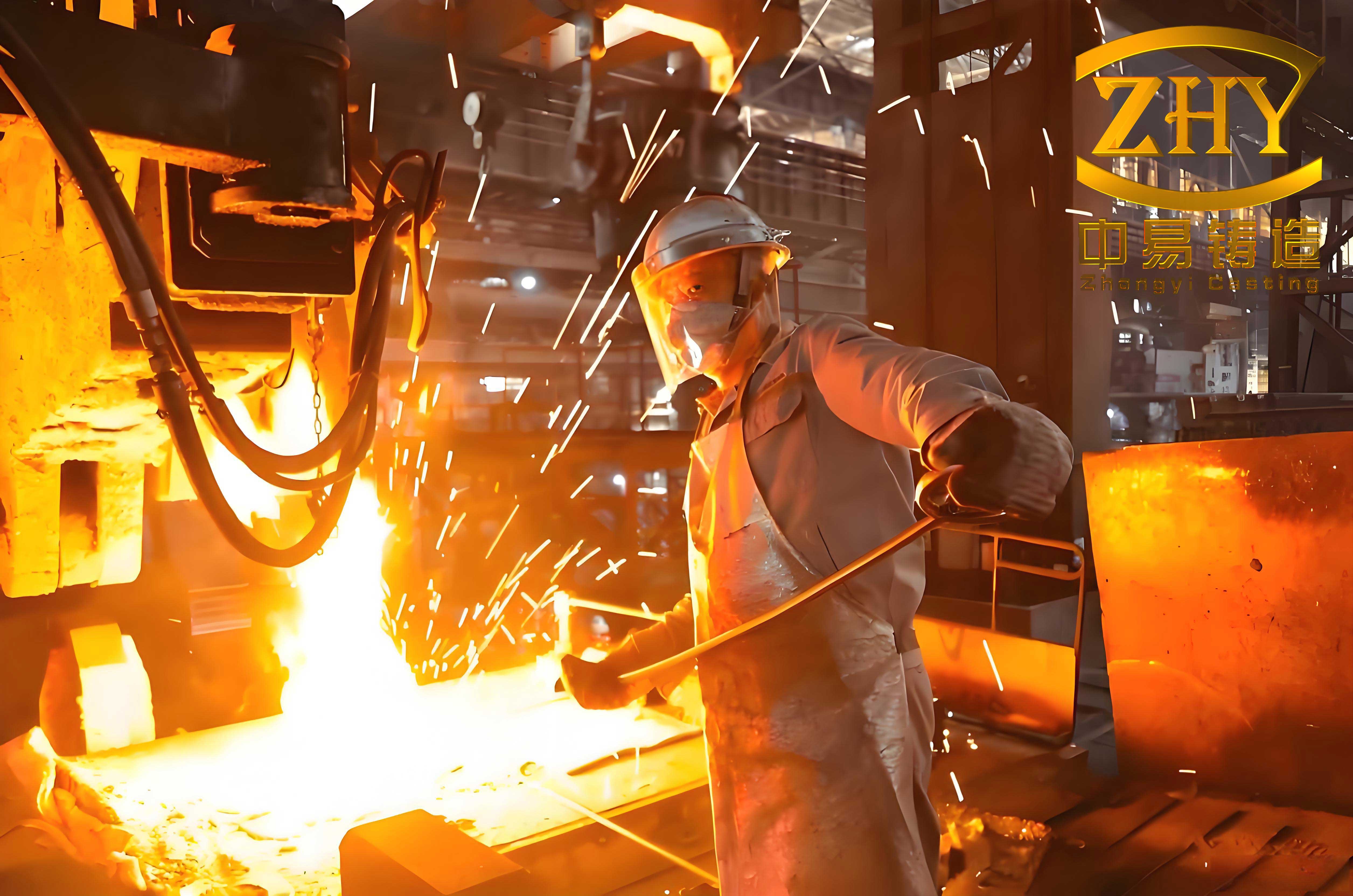
The simulation revealed that the total machining time for the lower mold was approximately 8 hours, with the cavity operations consuming the majority due to their complexity. I used post-processing to generate G-code for the CNC machine, which included commands for tool changes, coolant activation, and spindle control. This seamless transition from design to manufacturing underscores the power of CAD/CAM in lost wax investment casting, where precision is paramount. The image above illustrates a typical lost wax investment casting setup, highlighting the intricate relationship between mold design and final casting quality.
Throughout the design process, I encountered several challenges specific to lost wax investment casting. For example, the inclined cylindrical tube required a slider core that had to be precisely machined to avoid flash in the wax pattern. I addressed this by performing tolerance stack-up analysis using Pro/Engineer’s dimensioning tools, ensuring that cumulative errors did not exceed 0.05 mm—a strict requirement for lost wax investment casting to maintain dimensional integrity. Additionally, the reinforcing ribs necessitated thin-wall milling strategies to prevent tool deflection, which I simulated using finite element analysis (FEA) integrated into the software. The stress distribution during milling can be modeled as: $$ \sigma = \frac{F}{A} $$ where \( \sigma \) is the stress, \( F \) is the cutting force, and \( A \) is the tool cross-sectional area. By minimizing stress concentrations, I ensured the mold’s longevity for repeated lost wax investment casting cycles.
Quality control measures were integrated into the CAD/CAM workflow for the lost wax investment casting mold. I used coordinate measuring machine (CMM) data to verify critical dimensions, comparing them against the CAD model with a tolerance of ±0.01 mm. Statistical process control (SPC) charts were maintained to monitor machining variations, which is crucial in lost wax investment casting where consistency across multiple wax patterns is vital. The table below summarizes key quality metrics for the mold in the context of lost wax investment casting:
| Metric | Target Value | Measurement Method | Impact on Lost Wax Investment Casting |
|---|---|---|---|
| Surface Roughness (Ra) | 0.8 µm | Profilometer | Affects wax release and surface finish in lost wax investment casting |
| Dimensional Accuracy | ±0.02 mm | CMM | Ensures precise wax patterns for lost wax investment casting |
| Hardness (HRC) | 40-45 | Rockwell Tester | Enhances mold durability for lost wax investment casting production |
| Parting Line Flatness | 0.01 mm | Laser Scanning | Prevents flash in lost wax investment casting wax patterns |
The economic implications of CAD/CAM in lost wax investment casting mold design are significant. By reducing manual drafting and prototyping time, I estimated a 30% cost saving compared to traditional methods. The automated toolpath generation minimized material waste, which is especially important for aluminum alloys used in lost wax investment casting molds. Furthermore, the ability to simulate mold filling and solidification in associated software (e.g., CAE tools) allowed me to optimize the gating system for the lost wax investment casting process, reducing wax consumption and improving yield. The overall cost model can be approximated as: $$ C_{total} = C_{material} + C_{machining} + C_{design} $$ where each component is lowered through CAD/CAM integration, making lost wax investment casting more competitive for small-batch production.
Looking ahead, advancements in additive manufacturing could further revolutionize lost wax investment casting mold production. For instance, 3D printing of mold inserts with conformal cooling channels might enhance thermal management during wax injection, a critical aspect of lost wax investment casting. I explored this possibility by designing lattice structures within the Pro/Engineer model, though it was beyond the scope of this project. The convergence of CAD/CAM with Industry 4.0 technologies, such as IoT sensors for real-time monitoring, promises to elevate lost wax investment casting to new heights of efficiency and precision.
In conclusion, my experience designing a CAD/CAM system for a lost wax investment casting mold of connector parts demonstrates the transformative impact of digital tools on traditional manufacturing processes. From initial 3D modeling to final NC code generation, Pro/Engineer facilitated a seamless workflow that enhanced accuracy, reduced lead times, and lowered costs. The repeated focus on lost wax investment casting throughout this article underscores its enduring relevance in modern industry, where complex geometries demand sophisticated solutions. As I refine these techniques, I am confident that CAD/CAM will continue to drive innovation in lost wax investment casting, enabling the production of high-performance components with unparalleled consistency. The integration of simulations, parametric design, and automated machining not only streamlines mold development but also paves the way for smarter, more adaptive manufacturing systems in the realm of lost wax investment casting.
To further illustrate the technical details, I derived several formulas related to lost wax investment casting mold design. For shrinkage compensation, the adjusted mold dimension can be expressed as: $$ D_{adjusted} = D_{nominal} \left(1 + \alpha \Delta T + \beta\right) $$ where \( \alpha \) is the thermal expansion coefficient, \( \Delta T \) is the temperature change, and \( \beta \) is the wax shrinkage factor. In machining, the tool life equation for lost wax investment casting mold materials is: $$ T = \frac{C}{v^p f^q d^r} $$ where \( T \) is tool life, \( C \) is a constant, and \( p, q, r \) are exponents determined experimentally. These equations highlight the scientific rigor behind lost wax investment casting mold engineering.
Ultimately, the success of this project hinges on the holistic application of CAD/CAM principles to lost wax investment casting. By embracing digital twins, virtual testing, and data-driven optimization, I have crafted a mold that not only meets specifications but also exemplifies the future of manufacturing. As lost wax investment casting evolves, so too will the tools and methodologies, with CAD/CAM at the forefront of this exciting journey.