
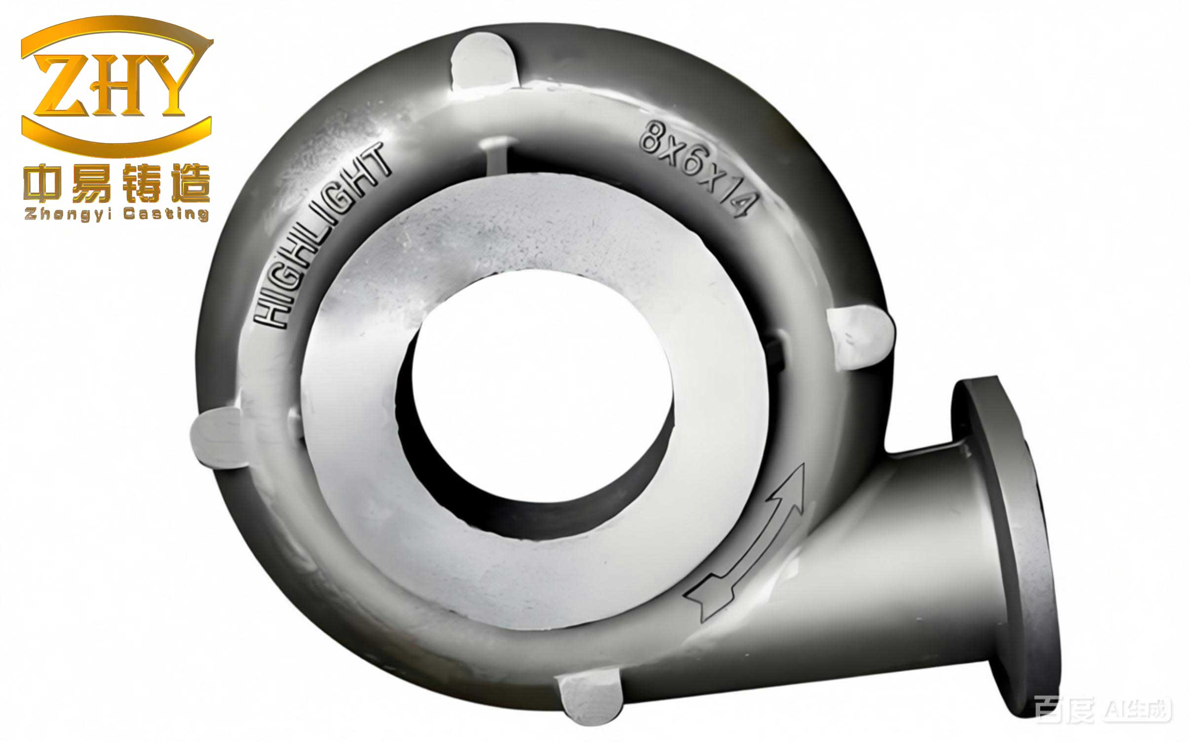
The presence of casting defects in finished components, especially those requiring pressure tightness, represents a significant challenge in the foundry industry. These imperfections can lead to catastrophic failures, non-compliance with stringent specifications, and substantial financial losses due to scrap. The pressure to minimize waste while meeting high-quality standards necessitates the development of reliable and effective repair methodologies. This article delves into the exploration and validation of a threaded plug repair technique, specifically designed to salvage pressure-retaining castings that fail hydrostatic tests due to leakage, thereby addressing a critical category of casting defects.
The core problem revolves around cast components with internal cavities designed to hold fluids under pressure. Common casting defects leading to leakage include micro-porosity, shrinkage cavities, sand inclusions, and cold shuts. A particularly insidious defect arises from the incomplete fusion of chaplets (core supports). During solidification, if a chaplet does not melt and fuse completely with the surrounding molten metal, it creates a discontinuous interface. Under hydrostatic pressure, this interface acts as a conduit for fluid seepage. Traditional repair methods like welding are often unsuitable for thin-walled sections or can induce thermal stresses that may worsen the defect. Therefore, a mechanical sealing solution is paramount.
1. Strategic Design of the Repair Scheme
When confronting leakage casting defects in thin-walled pressure boundaries, the choice of repair must consider geometry, material compatibility, and the fundamental principles of mechanical sealing. Two primary mechanical plugging approaches are generally considered:
- Interference Fit (Press Fit) Plugs: This method relies on elastic deformation to create a seal. The plug, with a diameter slightly larger than the hole, is pressed into place. The restoring force from the surrounding material creates a high-contact-pressure zone, preventing leakage. However, its effectiveness is governed by the material’s yield strength and the available wall thickness. The required engagement length \( L_e \) for a reliable press fit can be approximated by the shear area needed to withstand the internal pressure force:
$$ A_{shear} = \pi \cdot d \cdot L_e > \frac{P \cdot \pi \cdot (d/2)^2}{\tau_{allowable}} $$
where \( P \) is the internal pressure, \( d \) is the plug diameter, and \( \tau_{allowable} \) is the allowable shear stress of the casting material. For thin walls (e.g., 12-15 mm), achieving a sufficient \( L_e \) without compromising structural integrity is often impossible, making this method unsuitable. - Threaded Plugs: This method uses helical threads to convert rotational torque into axial clamping force, compressing a seal. Thread selection is critical. Coarse threads have larger pitches and clearances, offering poor sealing capability. Fine threads are better, but the choice between parallel (straight) and tapered threads is decisive. Parallel threads rely entirely on secondary sealing compounds (e.g., thread sealants) to fill the helical leak path. Tapered threads, such as the NPT (National Pipe Taper) or BSPT (British Standard Pipe Taper) standards, provide a superior mechanical seal. As the plug is tightened, the wedging action of the taper causes the threads to deform and engage more fully, significantly reducing the clearance and creating a metal-to-metal sealing interference at the root and crest of the threads.
For the case study of thin-walled engine frames (wall thickness ~12-15 mm) with pinpoint leakage defects, the tapered thread plug solution was selected. The small defect size (~Ø3 mm) and limited wall thickness dictated a small plug size. The ZG 1/8 (BSPT 1/8) taper thread was chosen for its appropriate diameter, standard availability, and excellent self-sealing characteristics under pressure.
| Method | Principle | Advantages | Disadvantages | Suitable Wall Thickness |
|---|---|---|---|---|
| Interference Fit Plug | Elastic deformation / radial stress | No threading required, relatively fast | Requires thick wall, risk of cracking thin sections, poor performance under thermal cycling | Substantial (e.g., >25 mm) |
| Tapered Thread Plug | Mechanical wedge & axial clamp force | Excellent seal, suitable for thin walls, mechanically locked, allows for sealant enhancement | Requires precise hole preparation (drilling, tapping) | Medium to Thin (e.g., 10 mm+) |
| Parallel Thread Plug + Sealant | Sealant fills thread clearance | Standard tools, simple | Seal integrity dependent entirely on sealant; risk of sealant extrusion under high pressure/ temperature | Medium |
2. Detailed Procedure and Engineering Validation
The successful implementation of a threaded plug repair for casting defects requires a meticulous, step-by-step procedure to ensure reliability.
2.1 Defect Localization and Marking
The casting must undergo a thorough hydrostatic test to pinpoint the exact location of all leakage casting defects. Each leak point is marked with a center punch and intersecting witness lines. This precise marking is crucial for the subsequent drilling operation.
2.2 Hole Preparation
This is the most critical phase in rectifying these casting defects. The quality of the tapped hole directly determines the sealing performance.
- Drilling: A pilot hole is drilled at the marked center. For a ZG 1/8 plug, the standard drill size for the small end of the taper is Ø8.5 mm.
- Taper Reaming: The straight hole is then converted to a precise 1:16 taper using a tapered reamer. This ensures the thread form will engage correctly along its entire length, maximizing the sealing interface. The final major diameter at the surface should be approximately Ø9.2 mm.
- Tapping: A ZG 1/8 taper tap is used to cut the internal threads. Consistent alignment and the use of cutting fluid are essential to produce clean, undamaged threads, free from tears or inclusions that could become new leakage paths—essentially creating new casting defects during the repair.
2.3 Plug Fabrication
The plug must be machined from a material compatible with the base casting to prevent galvanic corrosion, a potential future defect. For ferrous castings, a mild steel or low-alloy steel bar is suitable. The plug is machined to the ZG 1/8 external taper specification and includes a hex or square drive head for application of controlled torque during installation. The thread geometry can be defined by parameters:
$$ \text{Taper} = \frac{D_{major\_start} – D_{major\_end}}{L_{thread}} = \frac{1}{16} $$
Where dimensions are specific to the thread standard.
2.4 Assembly and Sealing
Both the tapped hole and the plug threads must be meticulously cleaned to remove oil, chips, and debris. A high-performance, pressure-resistant thread sealant (e.g., anaerobic or PTFE-based) is applied to the plug threads. The plug is then screwed into the hole and tightened to a specified torque \( T \), generating the essential axial clamping force \( F_a \). This force can be estimated by the simplified relationship:
$$ T \approx K \cdot d \cdot F_a $$
where \( d \) is the nominal diameter and \( K \) is a torque coefficient (typically 0.15-0.2 for lubricated steel threads). This force is what ultimately deforms the thread crests to create the seal and resist the internal pressure force trying to eject the plug.
2.5 Mechanical Locking (Staking)
To prevent the plug from vibrating loose during service, a positive mechanical lock is added. After final tightening and trimming the drive head flush with the casting surface, the perimeter of the plug-casting interface is staked at several points using a center punch. This localized plastic deformation of the casting material into the plug threads creates a permanent mechanical interference, safeguarding against rotation.
| Step | Action | Tool/Equipment | Key Parameter/Goal |
|---|---|---|---|
| 1. Identification | Hydrostatic test; mark leak points | Pressure test pump, center punch, scribe | Precise defect location |
| 2. Drilling | Drill pilot hole at marked center | Drill press, Ø8.5 mm drill bit | Accurate alignment, perpendicularity |
| 3. Reaming | Create 1:16 taper in hole | Tapered reamer (1:16) | Achieve correct taper profile |
| 4. Tapping | Cut internal ZG 1/8 threads | ZG 1/8 taper tap set, tapping fluid | Clean, full-form threads without tears |
| 5. Plug Machining | Machine external ZG 1/8 thread on plug stock | Lathe, thread gauge | Material compatibility, correct thread form |
| 6. Cleaning & Sealing | Clean threads; apply thread sealant | Solvent, brush, thread sealant | Remove contaminants; apply even sealant coat |
| 7. Installation | Screw plug in and torque to specification | Wrench, torque wrench | Achieve required axial clamping force \( F_a \) |
| 8. Trimming & Locking | Cut head flush; stake plug perimeter | Grinder, center punch, hammer | Flush finish; create permanent mechanical lock |
| 9. Final Verification | Re-perform hydrostatic test | Pressure test pump | Zero leakage at repair site and overall casting |
2.6 Final Verification and Performance Analysis
The ultimate validation of any repair for pressure-related casting defects is a repeat hydrostatic test. Castings repaired with the tapered thread plug method, following the procedure above, consistently passed the required pressure cycle without leakage. The effectiveness of the seal can be conceptually analyzed by considering the pressure required to overcome the thread engagement. The leak path is a complex helical labyrinth. The sealing capability \( P_{max} \) depends on the contact pressure \( \sigma_c \) generated by the axial force and taper interference:
$$ \sigma_c \approx \frac{F_a}{A_{contact}} $$
where \( A_{contact} \) is the effective thread contact area. For the seal to hold, \( \sigma_c \) must be significantly greater than the internal pressure \( P \) acting on the plug’s back area. The taper design ensures this condition is met and enhanced by the sealant filling any microscopic imperfections.
3. Broader Implications and Proactive Prevention
While the threaded plug technique provides an excellent salvage solution, the ideal strategy is to prevent the occurrence of leakage casting defects altogether. A holistic approach involves:
- Design Review: Collaborate with designers to avoid excessively thin sections in pressure walls and to specify appropriate draft angles and fillet radii to promote smooth metal flow and solidification.
- Process Optimization: Control pouring temperature, gating and risering design to minimize shrinkage and porosity. The use of simulation software to predict solidification and identify potential defect locations is invaluable.
- Core and Chaplet Design: Optimize chaplet design (size, shape, coating) to ensure complete fusion. Chaplets with excessive cross-sectional area act as heat sinks, leading to the very fusion casting defects they are meant to prevent. The required chaplet diameter \( d_c \) to ensure fusion can be related to the local modulus \( M \) of the casting section:
$$ d_c \propto \frac{1}{M} \quad \text{where} \quad M = \frac{V_{casting}}{A_{casting}} $$
Smaller chiplets in thicker sections and larger chiplets in thinner sections may be a better strategy. - Non-Destructive Testing (NDT): Implement pre-machining NDT methods like ultrasonic testing or radiography to identify internal casting defects (porosity, inclusions) early, allowing for alternative repairs before final machining and pressure testing.
| Casting Defect Type | Root Cause | Effect on Pressure Integrity | Preventive Measures |
|---|---|---|---|
| Microporosity/Shrinkage | Inadequate feeding, improper solidification sequence | Creates interconnected voids forming leak paths | Optimize riser design; use chills; control alloy composition. |
| Sand Inclusions | Erosion of mold/core, poor core strength | Non-metallic inclusion creates a discontinuity in the metal matrix | Improve mold/core coatings and binder systems; reduce turbulence during pouring. |
| Cold Shut | Poor fusion of two metal streams due to low temp or oxide film | Forms a linear discontinuity with poor mechanical bonding | Increase pouring temperature; improve gating design for smoother flow. |
| Chaplet Non-Fusion | Chaplet acts as a heat sink, causing premature solidification around it | Creates an unbonded interface between chaplet and casting | Use smaller, properly coated chiplets; ensure chaplet material and size are suitable for section thickness. |
| Gas Porosity | Entrapped gas from mold, core, or molten metal | Spherical pores that can be interconnected or surface-breaking | Improve mold/core venting; degas molten metal; reduce moisture in sand. |
4. Conclusion
The management of casting defects, particularly those compromising pressure tightness, is a critical aspect of quality assurance in foundry operations. The tapered threaded plug repair method has been demonstrated as a robust, reliable, and technically sound solution for salvaging thin-walled castings that fail hydrostatic tests due to localized leakage. Its success hinges on a disciplined procedure encompassing precise defect location, accurate taper hole preparation, correct plug fabrication, controlled installation with sealant, and positive mechanical locking. This method transforms a potential scrap loss into a conforming product, offering significant economic and resource efficiency benefits.
Ultimately, a dual-strategy approach is most effective: investing in process design and control to prevent the formation of leakage casting defects at the source, while maintaining validated, engineering-based repair techniques like the threaded plug method as a salvage tool for defects that inevitably occur. This comprehensive understanding of both prevention and repair solidifies the foundry’s capability to deliver high-integrity castings for demanding pressure applications.