
In modern foundry operations, the production of critical components like planetary gear brackets demands meticulous attention to detail, especially when employing automated systems such as the KW high-pressure molding line. These brackets are integral to planetary gear transmission systems, subjected to high external torques, and thus require superior mechanical properties, typically specified as QT600-3 ductile iron. However, the journey from process design to flawless castings is often fraught with challenges, primarily manifested through various casting defects. In this comprehensive account, I will detail our experience in designing, implementing, and refining the casting process for the planetary gear bracket under KW molding line conditions. The focus will be on identifying root causes of casting defects and implementing effective countermeasures, leveraging data, formulas, and systematic analysis to achieve consistent quality.
The initial process design was based on the factory’s existing KW high-pressure molding line, which utilizes green sand clay-bonded molds. The component, a planetary gear bracket with complex geometry including a central hub and three cylindrical bosses for gear assembly, required a robust casting approach. To optimize yield and utilize the molding line’s sandbox dimensions efficiently, a pattern layout of four castings per mold was adopted. The gating system was designed as a bottom-pouring type to ensure smooth metal flow and minimize turbulence. Given the need for rapid filling and effective slag trapping after spheroidization and inoculation, a partially choked gating system with the choke at the ingate was selected. The cross-sectional area ratio was established as:
$$ \sum A_{\text{sprue}} : \sum A_{\text{runner}} : \sum A_{\text{ingate}} = 1.1 : 1.45 : 1 $$
The total metal weight G was calculated as the weight of four castings plus 40% for the gating system, resulting in G = 135 kg. Using empirical factors, the pouring time t was set at 20 seconds. The choke area (ingate area) was determined via the Osborne Reynolds formula:
$$ A_{\text{ingate}} = \frac{G}{u \cdot t \cdot \sqrt{2gH}} $$
where u is the flow efficiency factor (taken as 0.4), g is gravitational acceleration, and H is the effective metallostatic head. This yielded \( \sum A_{\text{ingate}} = 17.6 \, \text{cm}^2 \), with trapezoidal sections of 42 mm/38 mm × 11 mm. The runner area was 24 cm² (26 mm/34 mm × 40 mm trapezoid), and the sprue area was 16.6 cm² (Φ46 mm circular). For feeding, edge risers were designed based on modulus calculations, sized at 90 mm × 90 mm × 160 mm with a 1.5° draft. This foundational design aimed to minimize common casting defects from the outset.
The production process involved several critical steps, each contributing to the final casting quality. The green sand properties were paramount; consistent control of moisture, compactability, permeability, and green strength was essential to prevent defects like sand inclusion and blowholes. Based on extensive laboratory testing, the target sand properties were established as shown in Table 1.
| Parameter | Target Range | Measurement Method |
|---|---|---|
| Moisture Content | 3.0% – 4.2% | Loss on drying |
| Compactability | 33% – 43% | Standard compactability test |
| Permeability | 180 – 210 | Standard permeability test |
| Green Compression Strength | 0.16 – 0.20 MPa | Universal sand strength machine |
| Return Sand Moisture | 2.0% – 2.5% | Control of system sand |
Mold hardness was continuously monitored using a sand hardness tester, with targets of HB 85–95 overall, HB 90–95 on the parting face, and HB 87–92 on sidewalls. This ensured adequate mold integrity to withstand metal pressure and reduce erosion, a common precursor to casting defects.
The melting charge consisted of 15% pig iron, 70% steel scrap, and 15% ductile iron returns, with additions of 27.1 kg graphite recarburizer and 5.4 kg electrolytic copper per ton of metal to achieve the desired composition. The pig iron composition is summarized in Table 2.
| Element | C | Si | Mn | P | S |
|---|---|---|---|---|---|
| Content (wt.%) | 4.34 | 1.04 | 0.15 | 0.048 | 0.018 |
Spheroidization was carried out using rare-earth magnesium ferrosilicon alloy (1.80–1.85% of metal weight, with 3% RE, 7–8% Mg) in a well-type treatment ladle via the sandwich method. Inoculation involved 75% ferrosilicon combined with a high-efficiency compound inoculant (0.15–0.20% of metal weight, containing Ba and Ca), applied both as base inoculation and stream inoculation during pouring. Copper addition stabilized pearlite and enhanced mechanical properties. The melting temperature was maintained at 1520–1540°C, with pouring temperatures controlled at 1420–1440°C initially, never falling below 1400°C. Post-pouring, castings were allowed to cool for 60–90 minutes before shakeout and cleaning.
Chemical analysis of trial castings from different heats (labeled A1 to A5) confirmed consistency within the QT600-3 range, as shown in Table 3. However, despite this compositional control, the initial trial production revealed several casting defects that necessitated deeper investigation.
| Sample | C | Si | Mn | P | S | RE | Mg | Cu |
|---|---|---|---|---|---|---|---|---|
| A1 | 3.67 | 2.21 | 0.53 | 0.025 | 0.014 | 0.025 | 0.053 | 0.53 |
| A2 | 3.71 | 2.52 | 0.52 | 0.022 | 0.010 | 0.026 | 0.036 | 0.41 |
| A3 | 3.60 | 2.56 | 0.56 | 0.026 | 0.015 | 0.023 | 0.041 | 0.44 |
| A4 | 3.68 | 2.18 | 0.48 | 0.022 | 0.012 | 0.024 | 0.043 | 0.52 |
| A5 | 3.62 | 2.20 | 0.53 | 0.020 | 0.016 | 0.028 | 0.045 | 0.57 |
The primary casting defects observed were blowholes (gas holes) and sand inclusions, particularly on the flange edges and non-machined surfaces. Additionally, mechanical properties (tensile strength and elongation) from test coupons attached to the flange failed to meet specifications, with metallographic analysis revealing excessive carbides (cementite) in localized areas. These casting defects posed significant risks to component performance and required immediate corrective actions.
Let’s delve into the analysis of each type of casting defect. Blowholes, characterized as rounded cavities with smooth walls, were predominantly located near the flange and boss regions. Their formation was attributed to two main factors: low pouring temperature and inadequate mold permeability. When the pouring temperature dropped to 1392°C in one trial, air entrapment and gas evolution from the mold increased, leading to blowholes. The mold sand, with high clay content and reduced permeability, hindered gas escape during solidification. The relationship between gas pressure and defect formation can be approximated by:
$$ P_{\text{gas}} = P_{\text{atm}} + \rho g h – \frac{2\gamma}{r} $$
where \( P_{\text{gas}} \) is the gas pressure in the bubble, \( P_{\text{atm}} \) is atmospheric pressure, \( \rho \) is metal density, \( h \) is depth, \( \gamma \) is surface tension, and \( r \) is bubble radius. Low pouring temperature increases metal viscosity, reducing bubble escape velocity and promoting entrapment. To address these casting defects, we implemented stricter controls: pouring temperatures were mandated at 1420–1440°C, with each heat monitored; old sand was partially replaced with new sand to reduce clay content and improve permeability; and vent channels were added to the mold to facilitate gas evacuation.
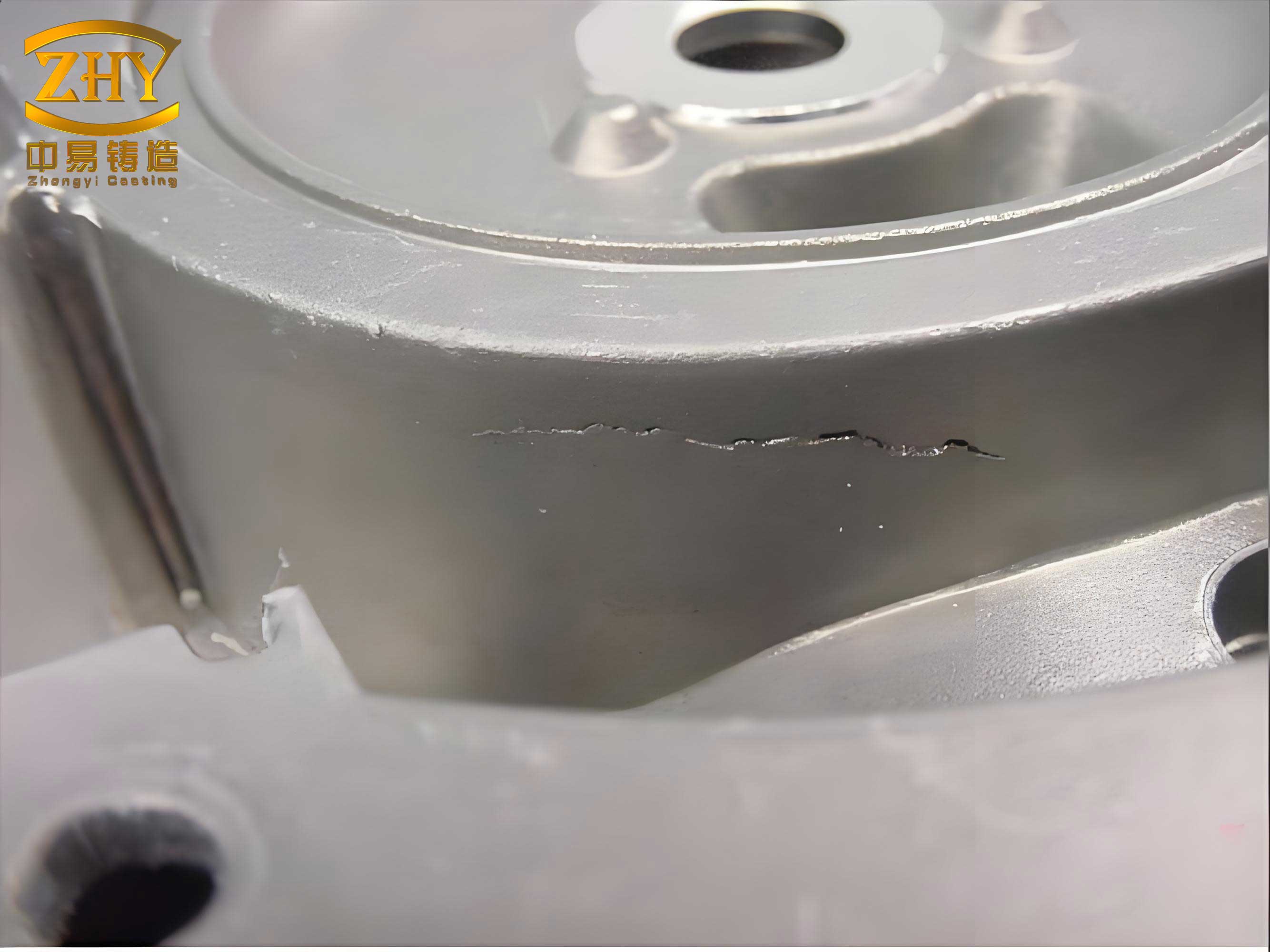
Sand inclusions, another prevalent casting defect, appeared as irregular cavities containing sand particles, often on the flange edges. Root causes included low surface strength of molds due to rapid moisture evaporation, loose sand particles in the gating system, insufficient mold compaction, and poor sand mixing leading to low green strength. The propensity for sand erosion can be modeled by the erosion potential E:
$$ E = k \cdot \frac{\rho_m v^2}{\sigma_s} $$
where \( k \) is a constant, \( \rho_m \) is metal density, \( v \) is flow velocity, and \( \sigma_s \) is sand bond strength. Low surface strength increases \( E \), making sand wash more likely. Corrective measures involved: reducing mold storage time to under 30 minutes before closing, with light water spraying on mold surfaces to maintain humidity; thorough cleaning of cavities and gating systems before closing; increasing mold compaction to achieve hardness above HB 90; enhancing sand mixing to ensure green strength above 0.18 MPa; regular slag removal from the furnace; and installing ceramic filters in the runner system to trap inclusions. These steps significantly reduced sand-related casting defects.
The third major issue was unsatisfactory mechanical properties, specifically low elongation and occasional low tensile strength in test coupons. Metallographic examination of flange samples showed areas with up to 95% pearlite and 3% cementite, indicating insufficient inoculation and premature shakeout. The presence of cementite, a hard and brittle phase, deteriorates ductility. The cooling rate and solidification time influence carbide formation, as described by the solidification time t_s:
$$ t_s = \frac{V}{A} \cdot \frac{\rho L}{k (T_m – T_0)} $$
where \( V/A \) is the volume-to-surface area ratio (modulus), \( \rho \) is density, \( L \) is latent heat, \( k \) is thermal conductivity, \( T_m \) is melting temperature, and \( T_0 \) is mold temperature. Fast cooling promotes carbides. To mitigate these casting defects, the stream inoculation rate was increased from 4 g/s to 8 g/s to enhance graphitization, and shakeout time was extended to a minimum of 60 minutes to allow for slower cooling and carbide decomposition. Additionally, copper content was fine-tuned to stabilize pearlite without excessive hardenability.
Beyond these, other subtle casting defects such as shrinkage porosity and misruns were monitored. The gating design was reviewed using fluid dynamics simulations to ensure balanced filling. The initial gating ratio was verified with the Bernoulli equation for incompressible flow:
$$ \frac{v_1^2}{2g} + \frac{P_1}{\rho g} + z_1 = \frac{v_2^2}{2g} + \frac{P_2}{\rho g} + z_2 + h_f $$
where \( v \) is velocity, \( P \) is pressure, \( z \) is elevation, and \( h_f \) is head loss. Adjustments to ingate sizes were made to reduce turbulence and air aspiration, further minimizing gas-related casting defects.
The implementation of these improvements yielded remarkable results. Post-refinement castings exhibited no visible blowholes or sand inclusions. Mechanical testing confirmed tensile strengths exceeding 600 MPa and elongations up to 7%, meeting QT600-3 specifications. Metallography showed a matrix of pearlite and ferrite with spheroidal graphite of grade 2-3, uniformly distributed. The process parameters were standardized, as summarized in Table 4.
| Process Stage | Parameter | Optimized Value | Rationale |
|---|---|---|---|
| Mold Sand | Moisture | 4.0–4.5% | Balance strength and permeability |
| Green Strength | 0.18–0.20 MPa | Prevent sand erosion defects | |
| Permeability | ≥200 | Reduce gas defects | |
| Melting | Pouring Temperature | 1420–1440°C | Avoid cold shuts and gas entrapment |
| Copper Addition | 0.4–0.6% | Stabilize pearlite, enhance strength | |
| Treatment | Spheroidizer Addition | 1.82% of metal weight | Ensure nodular graphite formation |
| Stream Inoculation Rate | 8 g/s | Suppress carbide formation, improve ductility | |
| Cooling | Shakeout Time | >60 minutes | Allow for carbide decomposition |
| Gating | Filter Usage | Ceramic filters in runner | Trap inclusions, reduce sand defects |
Throughout this project, the interplay between process variables and casting defects was evident. Each defect type—whether gas-related, inclusion-based, or metallurgical—required a tailored approach grounded in principles of fluid dynamics, heat transfer, and materials science. The high-pressure molding line, while automated, demanded rigorous control of sand properties, metal treatment, and pouring practices to achieve defect-free castings. The economic impact was also positive, as reduced scrap rates and rework lowered overall production costs.
In conclusion, the successful production of QT600-3 planetary gear brackets on the KW high-pressure molding line was achieved through systematic analysis and iterative improvement. By addressing the root causes of casting defects—such as blowholes via temperature and permeability control, sand inclusions via mold strength and filtration, and mechanical deficiencies via inoculation and cooling management—we developed a robust process. This experience underscores that in casting, vigilance against casting defects is perpetual, and continuous monitoring coupled with data-driven adjustments is key to quality assurance. The methodologies applied here, including formula-based design and empirical optimization, can be adapted to other complex castings, contributing to advancements in foundry technology and reliability.