
In the production of complex thin-walled castings, the occurrence of casting defects such as blowholes, sand inclusions, and core breakage presents a significant challenge to achieving consistent quality, dimensional accuracy, and pressure-tight integrity. These casting defects often stem from a confluence of factors related to mold design, core production, gating and venting systems, and process control. Based on extensive experience in a high-volume foundry environment, this analysis delves into the root causes of such casting defects and outlines systematic improvement strategies, supported by practical data and engineering principles.
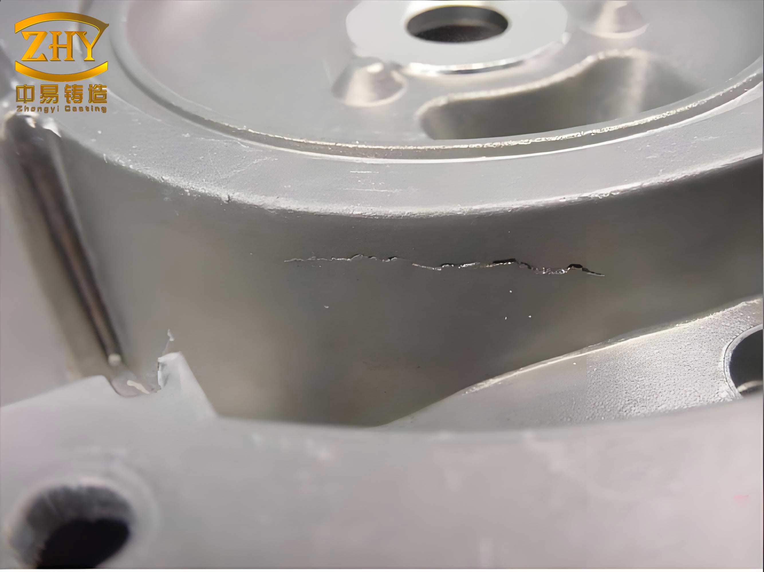
The case in point involves a clutch housing cast in gray iron (HT250), characterized by its intricate geometry, thin sections (minimum 5 mm), and a stringent requirement for leak-proof performance. The initial process employed a horizontally-parted mold with four cavities per mold, a bottom-gating system for tranquil filling, and extensive use of resin-coated sand cores. Despite careful planning, the production batch exhibited a high reject rate due to specific casting defects localized in predictable areas: blowholes at the top of the casting’s lower face, sand inclusions on the upper flange, and fractures at the connecting prints of large, suspended core assemblies.
Systematic Analysis of Casting Defects and Their Origins
A thorough investigation into these casting defects requires isolating each failure mode. The table below summarizes the primary defects, their locations, and the hypothesized root causes derived from process observation and metallurgical analysis.
| Defect Type | Typical Location | Hypothesized Root Cause | Governing Mechanism |
|---|---|---|---|
| Blowhole (Subsurface/Open) | High-point regions, near vent exits. | Inadequate venting of core and mold gases. | Gas pressure exceeds metal liquid pressure before solidification skin forms: $$ P_{gas} > \frac{2\gamma \cos\theta}{r} + \rho g h $$ where $P_{gas}$ is gas pressure, $\gamma$ is surface tension, $\theta$ is contact angle, $r$ is pore radius, $\rho$ is density, $g$ is gravity, $h$ is metal head height. |
| Sand Inclusion/Erosion | Vertical walls near mold edges, thick sections. | Low mold hardness in deep grooves leading to metal penetration and washing. | Erosion occurs when dynamic pressure of flowing metal exceeds sand’s cohesive strength: $$ \tau_{metal} > \sigma_{sand} $$ where $\tau_{metal}$ is fluid shear stress and $\sigma_{sand}$ is sand bonding strength. |
| Core Breakage/Shift | Small, connecting core prints between large core segments. | Insufficient strength of slender core prints to withstand buoyancy and handling stresses. | Core buoyancy force: $$ F_{buoyancy} = V_{core} (\rho_{metal} – \rho_{sand}) g $$ Print fails if $F_{buoyancy} \times L_{lever} > M_{print}^{strength}$, where $L_{lever}$ is the moment arm. |
1. Blowhole Defects: A Venting Challenge The concentration of blowholes at the highest point, adjacent to the placed vent slots, was a clear indicator of insufficient gas evacuation. While the original design included vents, they were shared between two large cores, creating a bottleneck. Core gases, predominantly from the pyrolysis of the resin binder in the coated sand, evolved rapidly upon contact with the molten iron. If the total available vent cross-sectional area is too small, the gas pressure within the mold cavity can build up to a critical level, forcing its way into the solidifying metal. Merely increasing pouring temperature to prolong fluidity is a double-edged sword, as it also increases the duration of core exposure to buoyant forces, potentially causing other defects like core shift. Therefore, the most direct corrective action is to redesign the venting system to provide a low-resistance escape path for gases from every major core volume.
2. Sand Inclusion Defects: A Mold Strength Issue The localization of sand washes on the upper flange’s vertical face, a feature originally formed by the sand mold near the mold wall, pointed to a mold compaction problem. In high-pressure molding lines, it is common for sand in deep, narrow recesses of the pattern to be under-compacted, a phenomenon known as “bridging.” This results in a local zone of low green strength and hardness. During pouring, the hydrodynamic forces of the iron stream can dislodge sand grains from this weak surface. The dislodged sand is then carried into the casting cavity, resulting in a sand inclusion. Measuring the mold hardness in these problematic areas confirmed values significantly below the specification, validating the hypothesis. The solution lies in either fundamentally improving compaction in these zones—which can be mechanically challenging—or redesigning the core/mold partition to have the critical surface formed by a strong core instead of the vulnerable mold sand.
3. Core Breakage Defects: A Structural Design Flaw The fracture at the slender connecting prints was a failure under combined stresses. The two large core segments were essentially cantilevered, linked only by three small cylindrical print interfaces. During handling, assembly, and most critically, during pouring, these prints were subjected to bending moments and shear forces. The buoyant force on the submerged core acts over its volume, creating a significant uplift moment. The strength of the small resin-sand print was inadequate to resist this. While using a higher-strength core sand might seem logical, it increases cost and gas generation, exacerbating blowhole issues. The strategic reinforcement of the critical stress points within the core assembly is a more targeted and effective approach.
Comprehensive Process Optimization and Solutions
Addressing these interconnected casting defects required a multi-faceted modification of the production process. The implemented solutions focused on enhancing gas evacuation, improving structural integrity, and eliminating vulnerable mold surfaces.
1. Optimized Venting System Design: The shared vent channel was eliminated. Instead, each major core was given its own dedicated, high-integrity vent passage. This vent was routed from the core’s geometric center or highest point directly to the outside of the mold. Ensuring vents are clear, of sufficient aggregate cross-sectional area, and connected to a low-pressure zone (atmosphere) is critical. The required vent area can be estimated based on core volume and gas evolution rates, aiming to keep the internal gas pressure below the metallostatic pressure at the critical location. A simplified guideline is: $$ A_v \ge k \cdot V_c $$ where $A_v$ is the total vent area, $V_c$ is the core volume, and $k$ is an empirical factor dependent on binder type and pouring rate. This change directly attacked the root cause of the entrapped gas casting defects.
2. Core Print Re-engineering and Reinforcement: For the sand inclusion problem, the core print for the upper core (#2) was significantly enlarged. This redesign transferred the formation of the problematic vertical flange wall from the weak mold sand to the surface of the strong, resin-bonded core. Since core sands have substantially higher hot strength and erosion resistance than green sand molds, this completely eliminated the source of sand washing in that area. This principle—using cores to form vulnerable or complex surfaces—is a powerful tool for preventing sand-related casting defects.
To solve the core breakage, internal reinforcement was introduced. A steel rod (core rod) was pre-placed in the mold of the slender print on the #2 core. During core shooting, the rod became integrally encapsulated within the sand. A corresponding socket was created in the mating #1 core. During core assembly, the rod was inserted into the socket with a high-temperature adhesive. This transformed the weak sand-to-sand joint into a mechanically reinforced steel-and-adhesive connection, dramatically increasing the bending strength and rigidity of the assembly at that critical junction. The reinforcement design must ensure the rod is fully embedded and does not fuse with the base metal, which could create a leak path. The increase in strength can be approximated by considering the rod as a beam within a sand matrix: $$ M_{new}^{strength} \approx M_{sand} + E_{steel} \cdot I_{rod} / L $$ where $E_{steel}$ is Young’s modulus of steel, $I_{rod}$ is the second moment of area of the rod, and $L$ is the effective length.
3. Complementary Process Controls: Beyond these specific design changes, a holistic view of process stability is essential to suppress all forms of casting defects. This includes:
- Gating System Tuning: Ensuring a pressurization ratio that promotes smooth, non-turbulent filling to minimize air entrapment and mold erosion.
- Sand System Management: Strict control of green sand properties (moisture, clay content, compressive strength) and core sand parameters (resin content, curing degree) to maintain consistent behavior.
- Pouring Practice: Consistent pouring temperature and speed within a defined window that balances fluidity for thin sections against gas evolution and core attack.
| Implemented Solution | Mechanism of Action | Primary Defect Addressed | Secondary Benefit |
|---|---|---|---|
| Dedicated, high-flow vent per core | Reduces gas back-pressure in cavity below critical threshold for metal penetration. | Blowholes | May reduce mistruns by allowing faster fill. |
| Enlargement of core print (#2) | Transfers critical surface formation from weak green sand to strong core sand. | Sand Inclusions | Improves dimensional accuracy of the flange. |
| Encapsulated steel rod in slender prints | Provides structural reinforcement at high-stress cantilever connections. | Core Breakage | Enables use of standard core sand, controlling cost and gas. |
| Holistic process parameter control | Creates a stable and repeatable manufacturing environment. | All Defects (General Prevention) | Improves overall yield and predictability. |
Generalized Principles for Defect Prevention in Complex Castings
The lessons learned from this specific case yield generalizable principles applicable to a wide range of castings prone to similar casting defects.
Principle 1: Gas Management is Paramount. For molds using organic binders (especially in cores), venting must be treated as a critical design function, not an afterthought. Vents must be sized adequately, directly connected to gas-generating volumes, and ensure a clear path to the exterior. The venting system’s efficiency is a key factor in preventing gas-related casting defects.
Principle 2: Design for Strength and Robustness. Core assemblies, particularly those with cantilevered sections or small joining areas, must be analyzed for structural integrity under handling and metallostatic forces. The strategic use of internal reinforcements (core rods, wires, or pre-cast inserts) is a highly effective method to prevent breakage and shift without resorting to expensive, high-gas core sands or problematic chaplets.
Principle 3: Minimize Vulnerable Mold Surfaces. In high-pressure or automated molding, deep, narrow grooves in the mold are potential weak spots. Wherever possible, the parting line and core/mold division should be planned to avoid creating such features in the green sand. Utilizing cores to form these geometries is a reliable strategy to eliminate a common source of sand inclusion casting defects.
Principle 4: Systems Approach to Process Control. No single parameter change exists in isolation. The interaction between pouring temperature, sand properties, gating design, and venting must be understood and controlled. A stable, well-documented process is the best defense against the sporadic appearance of casting defects.
In conclusion, the successful resolution of persistent casting defects in complex components like clutch housings hinges on a methodical root-cause analysis followed by targeted, often multi-pronged, process modifications. By understanding the physics and mechanics behind blowhole formation, sand erosion, and core failure, foundry engineers can implement solutions such as enhanced venting, core print redesign, and strategic reinforcement. These measures, grounded in practical engineering principles, effectively transform a problematic production process into a robust and reliable one, ensuring high-quality, defect-free castings that meet stringent performance requirements.