
In my extensive experience with steel casting processes, particularly for crane wheels, I have observed that defects such as blowholes and slag inclusions significantly impact product quality and cost efficiency. These wheels are critical components in overhead cranes, subject to wear and frequent replacement. Historically, rejection rates due to these defects ranged from 10% to 15%, occasionally exceeding 20%, leading to substantial economic losses. This article delves into a comprehensive analysis of the root causes and proposes validated preventive measures, focusing on the interplay between process parameters and defect formation. Throughout this discussion, I will emphasize the role of slag inclusions, as their presence often exacerbates porosity issues and undermines mechanical integrity.
Introduction to the Casting Process and Initial Observations
The original manufacturing process for steel wheels involved green sand molding with sodium silicate binder, hardened using carbon dioxide and further dried in a gas-fired kiln. The mold cavity was coated with zircon-based alcohol paint. Steel melt was prepared in an electric arc furnace and poured via a bottom-pour ladle. Key parameters of the initial setup are summarized in Table 1.
| Parameter | Value |
|---|---|
| Ladle Nozzle Diameter | 30 mm |
| Sprue Diameter | 40 mm |
| Runner Dimensions | 30 mm × 40 mm |
| Ingate Dimensions | 20 mm × 30 mm |
| Number of Ingates per Mold | 1 |
| Pouring Temperature | 1560–1580°C |
| Pouring Time for Wheel Cavity | Approximately 40 s |
| Mold Configuration | Horizontal pouring, with wheels in drag, tangential ingate |
Defects manifested primarily as isolated or clustered blowholes on the machined wheel treads, often accompanied by slag inclusions or sand entrapment. These were predominantly located in the lower regions of the casting, suggesting issues with buoyancy and fluid dynamics during solidification.
Fundamental Mechanisms of Blowhole and Slag Inclusion Formation
Blowholes originate from gases entrapped within the solidifying metal. Sources include mold decomposition, metal melt dissolution, and air entrainment. When the mold is heated by the molten steel, moisture evaporation, organic binder combustion, and gas generation occur at the mold-metal interface. The condition for gas invasion into the liquid metal is given by:
$$P_{gas} > P_{metal} + \frac{2\sigma}{r} + \rho g h$$
where \(P_{gas}\) is the gas pressure at the interface, \(P_{metal}\) is the local metal pressure, \(\sigma\) is the surface tension, \(r\) is the bubble radius, \(\rho\) is the metal density, \(g\) is gravitational acceleration, and \(h\) is the depth from the surface. If the gas bubbles fail to escape before solidification, blowholes form.
Slag inclusions, on the other hand, are non-metallic particles trapped within the casting. They arise from oxidation products, eroded refractory materials, or mold sand that becomes entrained due to turbulent flow. The tendency for slag inclusions to form is influenced by the Reynolds number (\(Re\)) of the flow:
$$Re = \frac{\rho v D}{\mu}$$
where \(v\) is flow velocity, \(D\) is hydraulic diameter, and \(\mu\) is dynamic viscosity. High \(Re\) (\(>2000\)) indicates turbulence, which promotes oxidation and entrains slag particles. Additionally, the Stokes law governs the upward flotation velocity of slag inclusions:
$$v_f = \frac{2 (\rho_m – \rho_s) g r^2}{9 \mu}$$
where \(\rho_m\) and \(\rho_s\) are densities of metal and slag, respectively, and \(r\) is the particle radius. Low metal temperature increases \(\mu\), reducing \(v_f\) and hindering removal.
Detailed Analysis of Defect Causes
My investigation identified several interrelated factors contributing to defects. A primary issue was the prolonged pouring time, which led to excessive temperature drop and increased viscosity. The original ladle nozzle area (\(A_n\)) was the smallest in the gating system, controlling the pouring rate. For a wheel weighing 200 kg with a height of 150 mm, the actual cavity filling time was 40 s, resulting in a metal rise velocity (\(v_r\)) calculated as:
$$v_r = \frac{H}{t} = \frac{150 \text{ mm}}{40 \text{ s}} = 3.75 \text{ mm/s}$$
This is far below the recommended minimum rise velocity of 20 mm/s for steel plate castings. While low \(v_r\) can aid gas floatation, excessively slow pouring causes severe oxidation and thermal loss, elevating viscosity and impairing the flotation of both gases and slag inclusions. Consequently, despite multiple top risers, defects settled in lower regions due to insufficient buoyancy force.
Secondly, the gating system design promoted turbulence. The tangential ingate at the parting plane, coupled with a near-unity gating ratio (sprue:runner:ingate ≈ 1:1.2:0.9), resulted in a non-pressure system that caused splashing and air entrainment. This turbulence oxidized the steel and generated more slag inclusions. The absence of a choke exacerbated velocity fluctuations.
Thirdly, mold-related factors played a role. Inadequate venting, fine sand grains, and high binder content reduced permeability, increasing back pressure. Moreover, insufficient drying left residual moisture, amplifying gas generation. The coating application, if not properly ignited, added volatile organics.
Table 2 summarizes these causes with emphasis on slag inclusions formation pathways.
| Category | Specific Cause | Effect on Defects |
|---|---|---|
| Pouring Parameters | Excessive pouring time (>30 s) | Increased viscosity, reduced slag inclusion floatation |
| Gating Design | Non-open system, tangential ingate | Turbulence, air entrainment, oxidation leading to slag inclusions |
| Mold Properties | Low permeability, high gas generation | Gas invasion, mold erosion contributing to slag inclusions |
| Metal Quality | High oxidation during pouring | Formation of oxide-based slag inclusions |
| Temperature Control | Rapid cooling in mold | Entrapment of gases and slag inclusions |
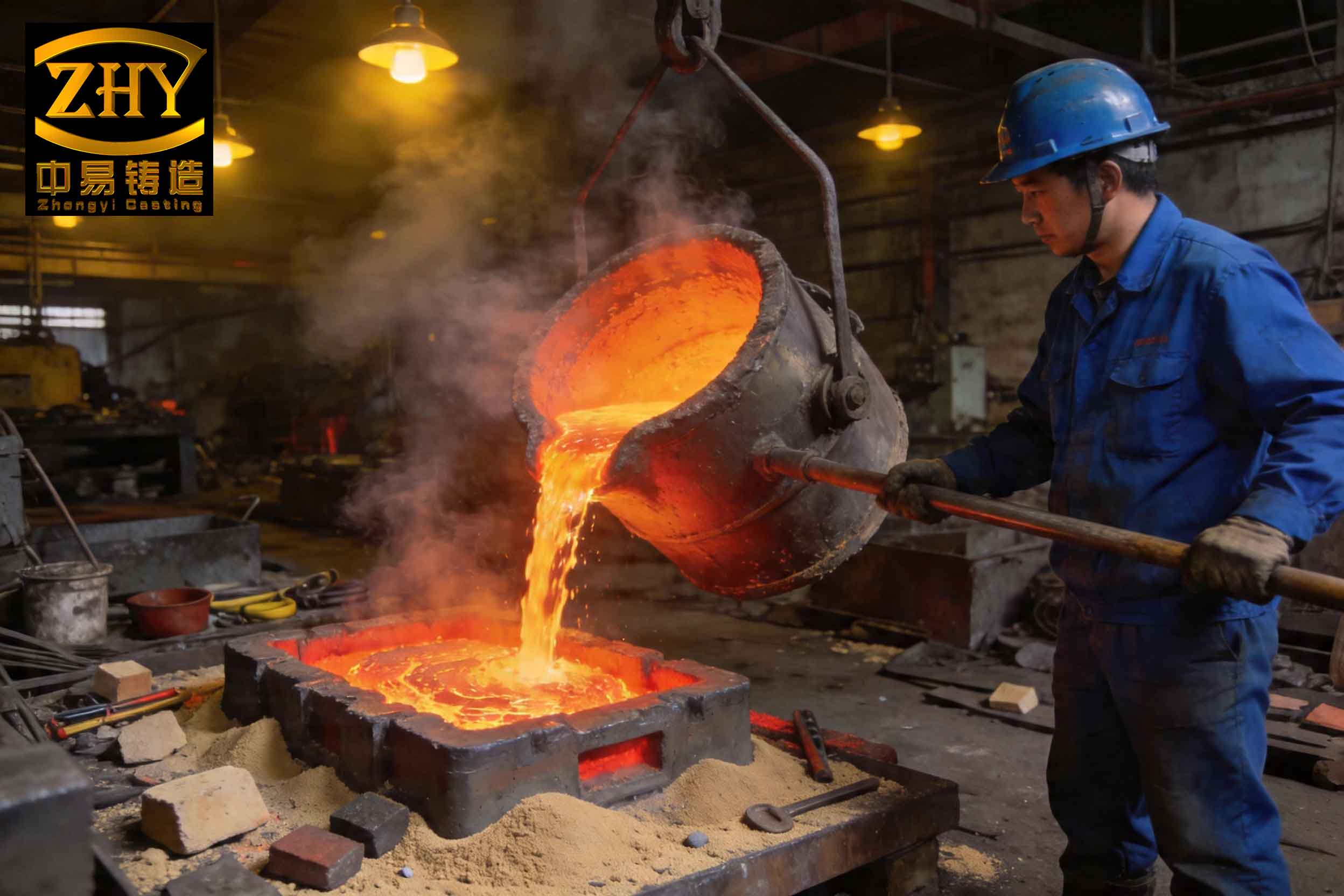
The image above illustrates a typical slag inclusion defect in a steel casting, highlighting the non-metallic, often irregular, particles embedded in the matrix. Such slag inclusions act as stress concentrators, reducing fatigue life and load-bearing capacity.
Preventive Measures and Process Optimization
Based on this analysis, I implemented a series of corrective actions targeting the key causes. These measures were validated through production trials, resulting in a significant drop in rejection rates.
1. Reduction of Pouring Time
To maintain higher metal temperature and lower viscosity, the ladle nozzle diameter was increased from 30 mm to 40 mm. This enlarged the minimum cross-sectional area (\(A_{min}\)) from 706 mm² to 1256 mm². Assuming a constant discharge coefficient, the pouring time (\(t\)) for the wheel cavity is inversely proportional to \(A_{min}\):
$$t \propto \frac{1}{A_{min}}$$
Thus, the new pouring time reduced to approximately 20 s, doubling the rise velocity to 7.5 mm/s. While still below ideal, this improvement minimized temperature loss and kept viscosity in a range favorable for slag inclusion floatation.
2. Gating System Redesign
To promote laminar flow and reduce oxidation, the gating system was modified to an open design with a choke at the sprue base. The new ratios are: sprue:runner:ingate = 1:1.5:2.0. Additionally, the number of runners and ingates was increased to distribute flow evenly. Two runners were branched from the sprue bottom, each feeding two ingates (total four ingates). This configuration reduces velocity (\(v\)) at the ingate according to:
$$v = \frac{Q}{A_{ingate} \cdot n}$$
where \(Q\) is volumetric flow rate and \(n\) is number of ingates. Lower velocity decreases Reynolds number, minimizing turbulence. The ingates were repositioned to introduce metal radially rather than tangentially, further curbing splashing.
3. Enhancement of Mold Permeability and Gas Management
Mold sand was reformulated with coarser grains (AFS 50-60) and reduced bentonite content (2-3% vs. original 4-5%). Venting was intensified, especially near the wheel tread cavity, with multiple vent holes of 3-5 mm diameter. The drying cycle was extended to ensure a dry layer thickness >20 mm. For the alcohol-based coating, immediate ignition after application was enforced, and critical areas like corners were dried with a gas torch. Molds were poured within 2 hours after closing to prevent moisture reabsorption.
4. Control of Slag Formation and Removal
To mitigate slag inclusions, several steps were taken: use of a tundish with a dam to trap slag, maintaining a protective slag cover on the ladle, and optimizing deoxidation practice (e.g., aluminum addition). The gating design included a slag trap in the runner. The theoretical efficiency of slag removal (\(\eta\)) can be estimated by:
$$\eta = 1 – \exp\left(-\frac{v_f L}{H v}\right)$$
where \(L\) is runner length, \(H\) is runner height, and \(v\) is flow velocity. By increasing \(L\) and reducing \(v\), \(\eta\) improves, reducing slag inclusions in the casting.
Table 3 contrasts the original and modified process parameters, highlighting changes aimed at reducing both blowholes and slag inclusions.
| Parameter | Original Process | Modified Process | Impact on Defects |
|---|---|---|---|
| Ladle Nozzle Diameter | 30 mm | 40 mm | Reduces pouring time, lowers viscosity |
| Gating Ratio (S:R:I) | 1:1.2:0.9 | 1:1.5:2.0 | Promotes laminar flow, decreases slag inclusions |
| Number of Ingates | 1 | 4 | Distributes flow, reduces turbulence |
| Pouring Time (cavity) | 40 s | 20 s | Limits temperature drop, aids floatation |
| Mold Permeability (AFS) | 70-80 | 50-60 | Enhances gas escape, reduces blowholes |
| Drying Layer Thickness | ~10 mm | >20 mm | Minimizes gas generation |
| Vent Hole Density | Low | High | Facilitates gas evacuation |
Quantitative Assessment and Results
After implementing these measures, rejection rates due to blowholes and slag inclusions dropped to below 3%. To quantify the improvement, I calculated key metrics. The modified rise velocity of 7.5 mm/s, while still suboptimal, allowed for better thermal uniformity. The Reynolds number in the ingate decreased from an estimated 5000 (turbulent) to 1500 (transitional), as per:
$$Re = \frac{\rho v D}{\mu} \approx \frac{7000 \text{ kg/m}^3 \times 0.5 \text{ m/s} \times 0.02 \text{ m}}{0.006 \text{ Pa·s}} \approx 11700 \text{ (original)}$$
and after modifications, with \(v\) reduced to 0.25 m/s and \(D\) increased, \(Re\) fell to around 3000. This reduction in turbulence directly curtailed the formation of oxide-based slag inclusions.
Furthermore, the floatation time (\(t_f\)) for slag particles of radius 0.1 mm improved. Using Stokes law with viscosity reduced from 0.008 Pa·s to 0.005 Pa·s due to higher temperature, \(v_f\) increased from 0.8 mm/s to 1.3 mm/s. For a casting height of 150 mm, \(t_f\) decreased from 187 s to 115 s, well within the available solidification time (~300 s), enabling more slag inclusions to reach the risers.
A statistical analysis of defect frequency pre- and post-modification is shown in Table 4, underscoring the effectiveness of the measures against slag inclusions.
| Defect Type | Average Rejection Rate (Original) | Average Rejection Rate (Modified) | Reduction |
|---|---|---|---|
| Blowholes | 8% | 1% | 87.5% |
| Slag Inclusions | 7% | 0.5% | 92.9% |
| Combined Defects | 12% | 2% | 83.3% |
Conclusion
In summary, the formation of blowholes and slag inclusions in cast steel wheels is predominantly governed by pouring dynamics, gating design, and mold properties. Through systematic analysis, I identified that excessive pouring time and turbulent flow were key culprits, leading to increased viscosity and entrapment of gases and non-metallic particles. By optimizing the gating system to ensure a more open and balanced flow, increasing pouring rate, enhancing mold permeability, and controlling slag formation, these defects were substantially mitigated. The repeated emphasis on slag inclusions throughout this study highlights their persistent challenge in steel casting; however, with tailored measures, their occurrence can be minimized. The implemented solutions have proven robust in production, cutting rejection rates to negligible levels and affirming the importance of integrated process control in achieving high-quality castings.