
The ongoing advancement of new urbanization and the development of metropolitan regions have created a sustained demand for efficient urban rail transit systems. The traction motor is a core component of these systems, and its housing is typically manufactured via casting due to the complexity of its geometry and the required mechanical properties. This article details the first-person perspective process of designing, simulating, and optimizing the casting process for a specific motor housing component made from ductile cast iron.
The housing is a critical structural component with demanding quality requirements. The designated material is QT500-7 ductile cast iron, known for its good combination of strength and ductility. The part features a predominantly thin-walled, barrel-shaped structure. Its overall envelope dimensions are approximately 760 mm in length, 500 mm in width, and 580 mm in height, with a final casting weight of about 160 kg. The main body wall thickness is designed to be 10 mm, but several functional features like mounting bosses create isolated heavy sections with a maximum thickness of up to 90 mm. This significant variation in wall thickness presents the primary challenge for sound casting production. The part is intended to be produced using a resin sand, hand-molding process. Non-destructive testing via X-ray radiography is required, with acceptance criteria set at Level 2 for critical areas and Level 3 for non-critical areas.
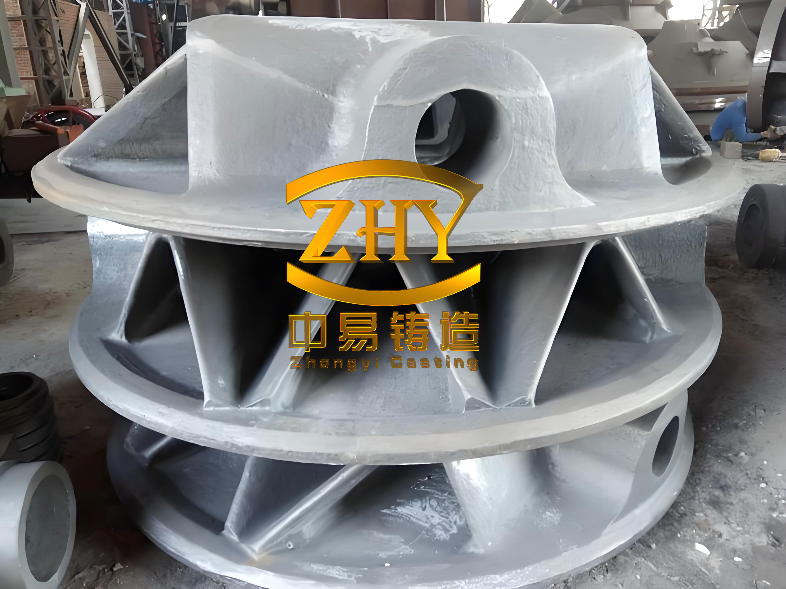
A preliminary analysis of the 3D model identified several potential isolated thermal nodes (hot spots) that are prone to shrinkage porosity defects in ductile cast iron. These are typically located at junctions where ribs, brackets, or other features intersect the main barrel wall. The key areas of concern are:
- Junctions between internal radial ribs and the barrel wall.
- Junctions of the upper and lower mounting brackets with the barrel.
- Attachment points for safety lugs.
- The junction where the cable connection box meets the barrel wall.
To accurately locate these hot spots and quantify their severity, numerical simulation software was employed from the initial design phase.
Foundry Process Design
Selection of Parting Line and Mold Orientation
Two principal orientations for pouring were evaluated. The first involved placing the barrel axis vertically (“vertical pour”). This orientation offers a calm mold filling sequence with a bottom-gating system and simplifies feeding for the internal rib hot spots. However, it requires numerous cores to form the outer contour and makes feeding the mounting brackets extremely difficult. The second orientation places the barrel axis horizontally within the parting plane (“horizontal pour”). This allows for a simpler two-part mold (split along the barrel’s axis), reducing core count, and positions the mounting brackets favorably for feeding. The challenge with this orientation lies in managing the thermal nodes at the internal ribs. Considering the overall feeding requirements and mold complexity, the horizontal pour orientation was selected.
Gating System Design
With the horizontal orientation confirmed, two gating approaches were considered. Option A used a large, ring-shaped runner along both end faces of the barrel in the drag (lower mold), feeding through flat gates. This promotes very tranquil filling but results in a low casting yield. Option B introduced runners along the parting plane that feed directly into the side walls of the barrel via flat gates. This yields a higher casting yield but carries a greater risk of turbulent metal entry. A balance was sought, and Option B was chosen with careful design to minimize turbulence. The existing flask dimensions dictated a one-casting-per-mold configuration. Two ingates were designed to introduce the molten ductile cast iron into the cavity. The key parameters were calculated as follows.
Pouring Time (t): Calculated using an empirical formula relating time to total metal mass.
$$ t = K \sqrt{G} $$
Where \( t \) is the pouring time in seconds, \( G \) is the total mass of metal in the mold (approx. 180 kg), and \( K \) is an empirical coefficient (taken as 1.85). The calculated pouring time was approximately 25 seconds.
Metal Rise Velocity (V): Verified to ensure proper mold filling.
$$ V = \frac{C}{t} $$
Where \( C \) is the height of the casting in the poured position (48 cm). The calculated rise velocity of 1.92 cm/s was within the acceptable empirical range for such castings.
Choke Area (S_choke): Determined using another standard foundry formula.
$$ S_{choke} = \frac{G}{0.31 \mu t \sqrt{H_p}} $$
Where \( \mu \) is the total flow loss coefficient (taken as 0.48 for ductile cast iron in this system), and \( H_p \) is the mean effective metal pressure head (calculated as 35 cm). The initial calculated area was 8.5 cm², which was empirically adjusted to 12 cm² for robustness.
A semi-restricted gating system ratio was adopted: \( \Sigma S_{sprue} : \Sigma S_{runner} : \Sigma S_{ingate} = 1.2 : 1.5 : 1 \). Consequently, the individual component areas were sized as shown in the table below.
| Gating Element | Calculated Area (cm²) | Selected Dimension |
|---|---|---|
| Sprue (Total) | 14.4 | Ø 40 mm (12.6 cm²) |
| Runner (Total) | 18.0 | 20 mm x 45 mm (per side) |
| Each Ingate (x2) | 6.0 | 15 mm x 40 mm (6.0 cm²) |
Application of Feeders and Chills
An initial solidification simulation was run with the basic gating system but without feeders or chills. The software clearly predicted the locations of significant thermal nodes, visualized as isolated liquid pockets in the late stages of solidification. The corresponding “modulus” (Volume/Surface Area ratio) at these hot spots was also extracted from the simulation, providing a quantitative measure of their severity. This simulation output was critical for designing an effective feeding strategy.
Based on the simulation, a combination of exothermic insulating feeders (risers) and chills was designed. Feeders were placed on the top (cope) side of the mounting bosses and other heavy sections to provide a reservoir of hot metal for feeding shrinkage. Chills were placed in the drag at the junctions of internal ribs to accelerate solidification locally and eliminate isolated hot spots. It is crucial to note that placing a feeder effectively increases the thermal modulus of the casting section it contacts. When selecting feeder size, the “feeding modulus” should be 1.2 to 1.3 times the modulus of the casting hot spot. For example, the simulation showed a hot spot modulus of 1.6 cm at an upper mounting boss. After placing the designed feeder, the effective modulus at that junction increased to 1.9 cm in the simulation, confirming the feeder’s adequacy. An undersized feeder would solidify before the casting section, causing shrinkage at the feeder neck.
The preliminary process layout, including gating, feeders, and chills, was modeled and simulated again. The results showed a favorable temperature gradient, with the feeders remaining liquid longest and directing solidification progressively towards them, significantly reducing the predicted risk of shrinkage porosity in the ductile cast iron casting.
Trial Production and Results
The first trial casting was produced according to the initial simulated process. After shakeout and cleaning, it was subjected to X-ray inspection. While most areas met specification, a localized region of shrinkage porosity was detected at the junction of the cable connection box and the main barrel wall. This area was classified as a non-critical zone but the porosity level exceeded the allowed Level 3.
Analysis of the simulation in hindsight, and the physical defect, indicated that the chosen feeder placement and chill arrangement were insufficient for this specific junction. An isolated liquid pocket formed here, cut off from the feeding paths, leading to micro-shrinkage. The solution was to augment the local cooling rate by adding two small internal chills specifically at this connection box junction in the mold. This modification aims to accelerate solidification, synchronize it with the surrounding wall, and minimize the isolated liquid volume. The optimized process with added chills was simulated once more, confirming the reduction in the thermal node.
A second trial was conducted with the modified process. The resulting ductile cast iron casting showed no significant shrinkage defects upon X-ray inspection, fully complying with the customer’s acceptance criteria. The chemical composition and mechanical properties of the casting, verified via separately cast test coupons, also met the QT500-7 specification requirements.
| Element | C | Si | Mn | P | S | Cu | Mg |
|---|---|---|---|---|---|---|---|
| Result | 3.64 | 2.83 | 0.38 | 0.029 | 0.010 | 0.40 | 0.045 |
| Property | Tensile Strength (MPa) | Yield Strength (MPa) | Elongation (%) | Hardness (HBW) |
|---|---|---|---|---|
| Specification (QT500-7) | ≥ 500 | ≥ 320 | ≥ 7 | 170 – 230 |
| Test Result | 570 | 423 | 15.5 | 200 |
Conclusion
The integration of numerical simulation software into the casting process design workflow for complex ductile cast iron components is invaluable. It simplifies traditional tasks, such as manual modulus calculation, and provides a visual and quantitative prediction of solidification patterns and defect formation. The successful development of this motor housing highlighted several key points. Firstly, simulating the initial design is essential for identifying non-obvious thermal nodes. Secondly, the selection and placement of feeders must account for the resultant increase in the local casting modulus. Finally, the prediction of shrinkage is highly sensitive to input parameters like chemistry and pouring temperature; therefore, areas with persistent isolated liquid pockets in the simulation, even if the shrinkage indicator is low, warrant serious attention as potential defect sites. The iterative cycle of simulation, physical trial, analysis, and process optimization enabled the rapid development of a sound casting process for this demanding ductile cast iron application in urban rail transit.