
Titanium alloy is widely used in the fields of aerospace and military industry. With the rapid development of titanium alloy casting technology, especially investment precision casting, the quality of titanium alloy castings has attracted more and more attention. In this paper, a simulation model of the casting forming of a titanium alloy hinge for a special automobile was established based on ProCAST software. The filling and solidification process of the hinge was analyzed, and the influence of risers with different sizes and shapes on the distribution of shrinkage cavities in the hinge was studied.
1. Introduction
Titanium alloy is widely used in aerospace, military and other fields. With the rapid development of titanium alloy casting technology, especially investment precision casting, the finished product quality of titanium alloy castings has received increasing attention. Using ProCAST simulation technology to analyze the filling and solidification of castings is beneficial to reduce the time of continuous trial and error in the product design process. In the design process of the casting riser, by simulating the dynamic feeding process of the riser, the technical difficulties in the process design can be overcome, and the product development time can be saved.
A titanium alloy hinge for the door of a special automobile is one of the typical parts that are prone to fracture during service. The structure is relatively simple, but the casting has an isolated hot spot, which is prone to shrinkage cavities. The commonly used ZTC4 titanium alloy for hinges is produced by the investment precision casting process. The processing process flow is: wax mold – coating – melting – pouring – mechanical processing – hot isostatic pressing – scanning – heat treatment – mechanical processing – finished product. During the production of the hinge, it was found that there were large pits at the connection between the body of the casting and the riser in multiple batches of castings, and the subsequent repair welding affected the performance of the casting, resulting in fractures during actual use.
The reason for the shrinkage cavities and other defects in titanium alloy castings is that the superheat degree of the titanium alloy liquid is low, and it is poured and cooled in a vacuum. Its feeding ability is not as good as that of cast steel, and the feeding distance is short. The shape and size of the titanium alloy riser have a great influence on the feeding effect. The shrinkage cavity problem at the root of the hinge is largely changed due to the change of the shape and size of the riser. The riser is a cavity used to store the molten metal in the mold during the casting process. It supplies metal when the casting is formed, and has the functions of preventing shrinkage cavities, shrinkage porosity, exhaust, and slag collection.
To address this issue, ProCAST software was used to simulate different sizes and shapes of risers, analyze the distribution of hot spots and shrinkage cavities, and obtain a riser scheme that can eliminate the shrinkage cavities, providing a reference for actual production.
2.Model Establishment
2.1 Hinge and Its Chemical Composition
The material of the hinge is ZTC4, which is a commonly used casting titanium alloy in the aerospace and military fields. This material belongs to a medium-temperature alloy and is one of the most widely used and most used titanium alloys. The chemical composition of the hinge used in this study is shown in Table 1.
Table 1 Chemical Composition of the Hinge (wt%)
| C | N | H | Fe | Al | V | Other Impurities | Ti |
|---|---|---|---|---|---|---|---|
| 0.02 | 0.11 | 0.02 | 0.0034 | 6.5 | 3.9 | 0.4 | Balance |
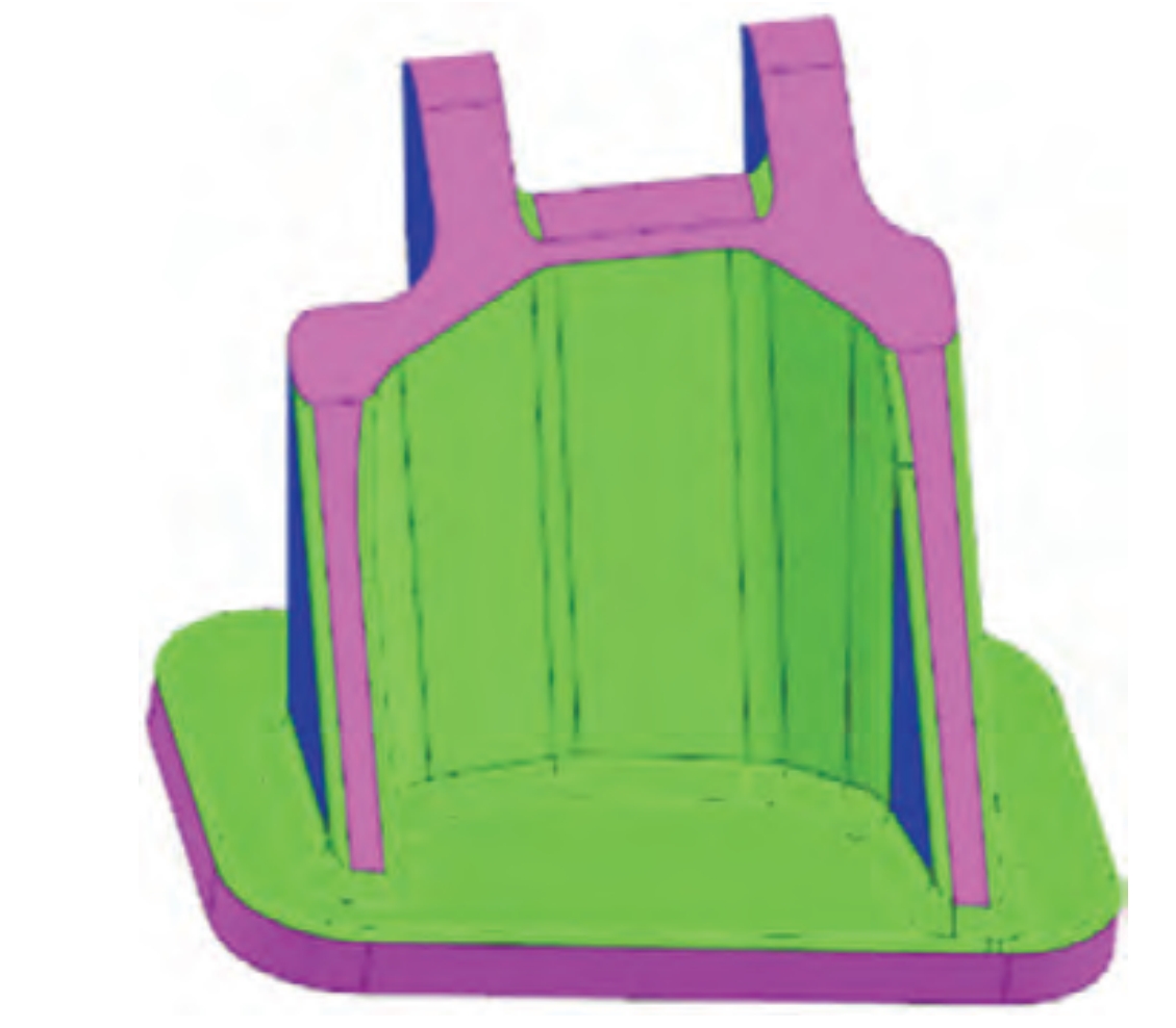
The three-dimensional diagram of the hinge is shown in Figure 1. The casting is a symmetrical small and medium-sized part with a square structure and an “H”-shaped protrusion. The overall dimensions of the casting are 136 mm × 140 mm × 146 mm, the minimum thickness is 7.7 mm, and the overall mass of the casting is 2.8 kg.
2.2 Finite Element Model
According to the different shapes of the castings, the commonly used shapes of risers include conical, trapezoidal elliptical, and trapezoidal with arc. The size or diameter of the riser for investment precision titanium alloy castings should not be less than 3 times the thickness of the feeding hot node, and the height of the riser is usually 1.5 – 2.0 times its thickness or diameter. In the design process of the riser, it is necessary to consider the smoothness and cleanliness of the connection between the riser and the casting to avoid inclusions, contamination, or even local chemical reactions.
Before designing the gating system of the hinge, the shrinkage cavity distribution of the casting without the riser was first analyzed. As shown in Figure 2, there is an isolated hot spot at the “H”-shaped protrusion of the square structure of the casting, which is prone to shrinkage cavities.
In this study, five different schemes of risers were set up for simulation analysis based on the shape of the hinge and the shrinkage cavity distribution during the solidification of the casting body, as shown in Figure 3. In Scheme 1, two trapezoidal gates with a slope were set at the bottom of the casting, and two round risers were set at the upper end perpendicular to the position of the root shrinkage cavity. In Scheme 2, based on Scheme 1, the round risers at the top were changed to trapezoidal risers with a slope to increase the feeding molten metal. In Scheme 3, based on Schemes 1 and 2, the casting was rotated 90 degrees counterclockwise, and a trapezoidal riser with a slope was set at the upper end perpendicular to the root shrinkage cavity. In Scheme 4, based on Scheme 3, a trapezoidal riser with a slope was set at the upper end of the bottom plate. In Scheme 5, based on Scheme 4, the riser perpendicular to the upper end of the root shrinkage cavity was changed to a conformal riser.
This study adopted the method of static pouring. For the gating system with different shapes and sizes of risers, the combined gating system designed in the five schemes is shown in Figure 4. In order to simulate the speed and accuracy of the calculation, different sizes of meshes were divided for different components. The mesh size of the sprue was set to 8 mm, the mesh size of the runner was set to 6 mm, the size of the riser and the casting was set to 3 mm, and the finite element model was set up. And because the mold shell needs to be coated with 11 layers of slurry in the actual production process, in the simulation process, the thickness of each layer of slurry was approximated to be 1.3 mm, that is, the thickness of the mold shell was set to 14 mm, and a total of 1,554,465 body meshes were divided, and the final finite element model is shown in Figure 5.
In the actual production process, the temperature of the mold before pouring also affects the fluidity and filling ability of the titanium alloy. In the simulation process, the initial temperature of the pouring mold shell was set to 300 °C, the pouring temperature of the molten metal was set to 1720 °C, the pouring time was set to 5 s, and the other related simulation parameters are shown in Tables 2 – 4.
Table 2 Related Parameters in the Simulation
| Ambient Temperature (°C) | Initial Mold Temperature (°C) | Pouring Temperature (°C) | Pouring Time (s) | Radiation Coefficient of Pouring Furnace | Pouring Speed (kg·s^-1) |
|---|---|---|---|---|---|
| 30 | 300 | 1720 | 5 | 0.91 | 5.76 |
Table 3 Heat Transfer Coefficient between Molten Metal and Mold Shell
| Temperature (°C) | 0 | 25 | 1600 | 1650 | 2000 |
|---|---|---|---|---|---|
| Heat Transfer Coefficient (W·m^2·K^-1) | 30 | 30 | 100 | 600 | 600 |
Table 4 Emissivity of the Mold Shell
| Temperature (°C) | 30 | 600 | 800 | 1000 | 1200 | 1400 | 1600 | 1800 | 2000 |
|---|---|---|---|---|---|---|---|---|---|
| Emissivity | 0.9 | 0.71 | 0.62 | 0.56 | 0.51 | 0.48 | 0.47 | 0.46 | 0.45 |
3. Simulation Results and Analysis
3.1 Analysis of Hot Spots under Different Risers
The temperature field during the filling process of the hinge is shown in Figure 5. When the casting was filled for 3 s, the molten metal began to flow into the mold from the runner, and the flow rate of the molten metal was 0.5 m/s. When the filling time was 3.5 s, that is, the filling rate was 70%, the flow rate of the molten metal in the mold was 0.33 m/s. When the filling time was 4 s, the filling rate was 80%, and the flow rate of the molten metal stabilized at 0.3 m/s. Until the filling was completed at 5 s, the flow rate of the molten metal in the mold was stable at about 0.3 m/s, and there was no obvious turbulence, splashing, or incomplete filling, that is, the filling of the molten metal was stable, and the design of the gating system was reasonable.
Due to the complex structure and pouring process of the casting in the multi-scheme simulation analysis, in order to ensure smooth and rapid filling and complete and smooth filling, it is necessary to prevent the occurrence of cold shuts during the filling process. As the molten metal flows, the temperature of the high-temperature titanium liquid decreases, the molten metal flows into the cavity of the casting, and gradually flows into the riser. As the distance of the molten metal movement increases, the temperature of the bottom runner gradually decreases. The position closer to the gate has a higher temperature, and vice versa. And according to the analysis of the structure of the casting, at the same position of the casting, the temperature at the thinner wall position is lower than that at the thicker wall position.
The filling and solidification affect the quality of the subsequent casting. Titanium alloy castings are prone to defects such as shrinkage cavities, shrinkage porosity, porosity, and inclusions during solidification. Therefore, the design of the gating system needs to meet the requirements that the liquid titanium can quickly and smoothly fill the mold cavity from the same direction from bottom to top without generating eddies, splashes, and interruptions, and the gas in the cavity can be smoothly discharged out of the mold.
A typical node at the final solidification position of the casting was selected to track the change of its temperature over time. As shown in Figure 8, at the initial stage of filling, the molten metal entered the gate, and the temperature of the node was 1720 °C. As the filling progressed, the molten metal flowed through the sprue, runner, and shunt into the node, and the temperature of the node was maintained at about 1650 °C when the balance between the flow of the molten metal and the cooling of the node itself was reached. At 158.4 s, the temperature of the node dropped to 1600 °C, and the node was completely solidified. After 158.4 s, the metal flow channel was closed, no metal flowed into the node, and the temperature of the node continued to decrease and cooled to room temperature with the furnace. At 158.4 s, the temperature of each part of the casting dropped below the solidus temperature, indicating that the casting had completely solidified, and the free shrinkage of the molten metal at the position of the isolated hot spot formed a void, that is, the shrinkage cavity.
Therefore, it was attempted to design the fifth type of riser according to the shape of the casting, that is, the shape of the maximum wall thickness. According to the solidification hot node, it can be known that the riser neck solidified after the maximum wall thickness, and the casting can completely rely on the riser for feeding, indicating that this kind of riser design is more reasonable.
3.2 Analysis of Shrinkage Cavities under Different Risers
Figure 9 shows the simulated distribution of shrinkage cavities with a porosity of 30 under different risers. It can be seen from the figure that the shrinkage cavities of the first two schemes are slender and concentrated in the thick reinforced area perpendicular to the feeding of the riser. The large shrinkage cavity of Scheme 1 is 2.86 cm^3, and the size of the slender large shrinkage cavity of Scheme 2 is 2.95 cm^3. This kind of large shrinkage cavity has a great impact on the strength, plasticity, and toughness of the casting, and must be avoided. In order to avoid the slender shrinkage cavities as shown in Schemes 1 and 2, the casting in Schemes 3 – 5 was rotated 90 degrees counterclockwise. This kind of molding method can effectively avoid the slender shrinkage cavities. However, there is a shrinkage cavity of 2.62 cm^3 at the root of the casting riser in Schemes 3 and 4, and the shrinkage cavities in other parts are basically effectively eliminated. In Scheme 5, the top riser was designed according to the shape of the casting. According to the post-processing results, it can be seen that the shrinkage cavities in the casting are almost completely eliminated, and the overall defects of the casting are almost none. Because the casting will be subjected to hot isostatic pressing treatment later, the shrinkage cavities in Scheme 5 can be completely removed according to experience, meeting the production requirements of the hinge.
4.Experimental Verification
In order to ensure the comparability of the experimental results and the simulation results, the casting was directly pressed with a metal mold to make a wax mold. In order to prevent the shrinkage of the wax mold, the wax mold was placed in an integral molding cold wax, and the shrinkage rate was designed as 1.5%. The pickling amount was 0.6 mm on one side. According to the conformal riser designed in Scheme 5, the molding situation is shown in Figure 10, and it was poured statically in a 100 kg vacuum consumable shell furnace at 1720 °C.
The mechanical properties of the casting were obtained through the room temperature tensile test. The experimental equipment used was the Shimadzu AGS-X3000KNX universal material testing machine. Two R5 samples attached to the casting and subjected to hot isostatic pressing treatment together (that is, holding at 910 °C for 2 h under an argon pressure of 120 MPa, and air-cooling to below 300 °C with the furnace) were taken for the test according to GB/T 228.1.
By using the method of molding cold wax + metal mold + static pouring, the contour dimensions of the casting were effectively guaranteed. The casting was subjected to dimensional inspection, including the comparison with the casting digital model by using the articulated arm scanning. The casting was inspected, and the initial inspection of the dimensional deviation within ±0.5 mm and the 100% dimensional inspection of the casting were carried out by professional inspectors according to the casting drawing and the PCP dimensional control table for the final inspection of the casting dimensions. The structural contour dimensions within 150 mm of the casting can be controlled within ±0.3 mm. The surface of the casting basically has no visible flow marks, cold shuts, and micro-cracks. After hot isostatic pressing, there is no obvious pit at the root of the casting, as shown in Figure 11. The internal quality of the casting was detected by X-ray, and it was carried out according to the MFS0705 regulation and evaluated according to the ASTM E 192 standard X-ray reference negative. As shown in Table 5, the internal defects of the casting were evaluated according to the wall thickness of the casting. The hinge casting used Kodak 125X X-ray negative, the fluorescence inspection method used Class I A method, and the fluorescence liquid had a sensitivity of Level 3. The X-ray detection results were consistent with the simulation results, as shown in Figure 12. The X-ray detection results of the casting showed that the shrinkage cavity was on the riser, and there was almost no shrinkage cavity in the overall casting. After detection, the internal quality and fluorescence surface quality of the hinge casting were good, the one-time qualification rate of the casting fluorescence was more than 70%, and the one-time qualification rate of the X-ray detection was more than 75%. The number of defects was small, and after a small amount of repair, the casting finally met the requirements of the technical conditions. And the room temperature tensile mechanical properties of the casting after hot isostatic pressing and annealing treatment are shown in Table 6, which met the requirements of the technical agreement and the requirements for putting into production.
5. Conclusions
(1) Using ProCAST technology to analyze the filling and solidification of castings is beneficial to reduce the time of continuous trial and error in the product design process. During the design process of the casting riser, by simulating the dynamic feeding process of the riser, the technical difficulties in the process design can be overcome, and the product development time can be saved.
(2) Through multi-scheme simulation analysis and adopting different gating and riser schemes, the problem of concentrated shrinkage cavities at the thick hot spot at the root of the casting was solved.
(3) Using the conformal riser structure design, the shrinkage cavity was reduced by 94.8% compared to before, and the shrinkage cavity at the root of the casting was reduced from 2.11 cm^3 to 0.11 cm^3, and the shrinkage cavity was almost completely eliminated. X-ray flaw detection was carried out, and the detected shrinkage cavity defects were consistent with the simulation results. The one-time qualification rate of the casting fluorescence was more than 70%, and the one-time qualification rate of the X-ray detection was more than 75%. The number of defects was small, and after a small amount of repair, the casting finally met the requirements of the technical conditions.