
Abstract
The technical challenges encountered during the trial production of K6 swing bolster steel castings for railway freight cars. Specifically, we designed a one-piece splicing refractory material three-way gating system to solve issues such as surface sand inclusion and misrun. Additionally, a dedicated exhaust bracket was introduced on the side bearing box to improve venting and eliminate misrun defects. The new process significantly enhanced casting quality and reduced repair costs. This paper presents a detailed analysis of the casting process, the design of the gating system and exhaust bracket, as well as process validation and conclusions.
1. Introduction
The K6 swing bolster for railway freight cars is a critical component with a complex structure and uneven wall thickness, making it difficult to cast. The material used, B+ grade steel (ZG25MnCrNi), exhibits poor fluidity, which further complicates the casting process. In this study, we aimed to optimize the casting process to improve the quality of the K6 swing bolster steel castings.
2. Structural Characteristics and Technical Requirements
2.1 Structural Characteristics
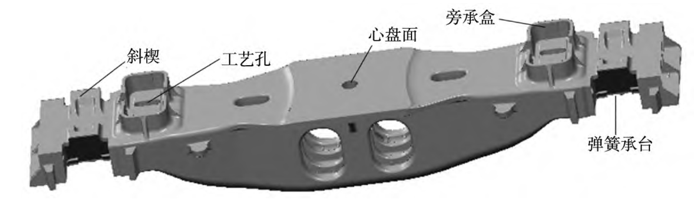
The K6 swing bolster for railway freight cars is an arcuate box-type structure with complex geometry. it has a contour size of 2,492 mm × 440 mm × 350 mm and a mass of 640 kg. The bolster features four process holes and internal rib plates connecting the upper and lower walls. The average wall thickness at the bottom is 33 mm, with the thickest part at the arcuate transition being 36 mm. The wall thickness is uneven, especially at the connections between the middle rib plates and the center plate surface and the bottom arcuate surface. High dimensional accuracy is required for assembly mating surfaces such as the spring bearing surface, the distance between the two wedges, and the side bearing box.
2.2 Technical Requirements
The K6 swing bolster is manufactured from B+ grade steel (ZG25MnCrNi) with specific chemical, mechanical, and non-metallic inclusion requirements.
3. Production Status and Problem Analysis
Our company uses an environmentally friendly, renewable ester-hardened water glass sand automation production line for molding, and a 25-ton LF bottom-pouring large refining ladle for refining and pouring. The main issues encountered during the production of K6 swing bolsters include:
- Misrun defects in the side bearing box.
- Severe surface sand inclusion .
- Poor venting during pouring.
4. Original Process Introduction and Problem Analysis
The original process for the swing bolster was set up as two pieces per box, using a central pouring system with ester-hardened water glass mixed type sand (30% new sand + 70% reclaimed sand). The gating system, including the ingate and cross gate, was formed by the sand mold. Several issues arose during actual production:
- Turbulence and gas entrapment due to the high pressure head of the large refining ladle and the long-term erosion of the cross gate by molten steel.
- Slow molten steel flow and long filling time due to the small flow control cross-sectional area of the original gating system.
- Poor venting at the side bearing box, leading to misrun defects.
5. Process Optimization and Improvement
5.1 Newly Designed One-Piece Splicing Three-Way Gating System
A one-piece splicing refractory material three-way gating system was designed. The specific structure includes right-angle elbows at both ends of the cross gate for splicing. The ingate and downsprue of the three-way gating system are installed and positioned, and the entire gating system is moved to the outer end of the casting. Pouring pipes are pre-embedded in the cores at the side ends of the runners to ensure smooth pouring and communication between the upper and lower ingates at the casting ends. The advantages of this design include:
- Shortened cross gate length for smoother molten steel flow and reduced turbulence and gas entrapment.
- Improved pouring speed for faster mold cavity filling and reduced erosion of the sand mold.
- Increased casting yield.
5.2 Dedicated Exhaust Bracket for Side Bearing Box
The height of the air vent pins on the original side bearing box was reduced and repositioned on the upper mold. A dedicated exhaust bracket for the side bearing box was designed based on the positioning system. The advantages of this design include:
- Elimination of the need for electric drilling of vent holes after sand compaction.
- Prevention of sand inclusion caused by floating sand falling into the mold cavity during the pouring line movement.
- Significant reduction in operator workload.
5.3 Use of High-Temperature Resistant Porous Grid Venting Valves
High-temperature resistant porous grid venting valves were used to replace the wedge venting risers. These valves prevent floating sand from entering the mold cavity and reduce steel waste and quality issues associated with cutting the risers.
5.4 Development of New Special Tooling
A dedicated sand box tooling for the swing bolster was designed, taking into account the structural characteristics and parting line position, as well as the actual production situation of our company’s ester-hardened water glass sand automation production line. The upper sand box completely avoids the vent hole positions of the side bearing box exhaust bracket and the one-piece splicing three-way pouring gate, further reducing the height of the upper sand box, effectively reducing sand usage, and significantly lowering the total gas generation of the sand mold.
6. Process Validation
The mold for the K6 swing bolster was repaired and modified according to the requirements of the one-piece splicing three-way gating system. A side bearing box exhaust bracket and dedicated sand box were designed, and small-batch process trials were conducted for validation. During the trial production, the sand mold stripping and coring processes were normal, and visual inspection after mold opening showed smooth pouring and complete mold filling. Dissections were performed at specified locations according to the technical standards for railway freight car steel cast swing bolsters and side frames. Inspection of the dissection planes revealed no significant defects such as shrinkage porosity, sand inclusion, or misrun, meeting the standard requirements.
In the process validation and production practice, it was found that the use of the side bearing box exhaust bracket and high-temperature resistant porous grid venting valves significantly improved the phenomenon of floating sand entering the mold cavity through the side bearing box vent holes during the transfer of the sand mold on the molding production line. The manual drilling process was eliminated, improving production efficiency. The pouring process was smooth, and there was no cracking or falling of the high-temperature resistant porous grid venting valves into the mold cavity. The surface sand inclusion of the castings was reduced, and there was no misrun in the side bearing box.