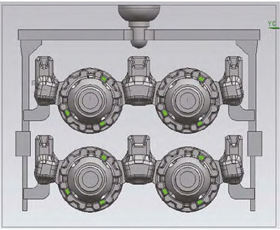
process scheme
The flange design of the differential housing is thin, with a large number of windows and punching holes, and the client has high requirements for internal porosity. The preliminary process design adopts a double riser scheme. Install a riser at each flange position corresponding to two pin holes on the casting. Based on the weight and structural dimensions of the castings, a rectangular riser is designed to improve the production rate of the process. The edges of the rectangular riser are rounded with a rounded angle R10 to remove weight, and a common riser is reasonably arranged in the middle position. Finally, a design scheme of 2 castings corresponding to 3 risers is adopted. Based on multiple individual simulation results, the size of the single riser used on both sides was selected as 120 mm × 43 mm × 50 mm. In order to achieve the best shrinkage effect, the riser neck was designed to maximize its size, removing the height of the separation stop by 0.5 mm. The design height of the riser neck was 7.7 mm, and the length of the riser neck was designed to be 55 mm, which means the cross-sectional area of the riser neck reached 423 mm2; To reduce the weight of the riser unit and meet the needs of liquid shrinkage, a 15mm weight removal pressure groove is designed at the top of the riser, and a separation block is designed at the bottom of the riser with a height of 15mm. The final weight of the riser unit on both sides is 2.1 kg, with a module of 6mm. Similarly, the middle shared riser is designed according to the single riser design, with a shared riser size of 120 mm × 55 mm × 50 mm, a bottom pressure groove of 15 mm, and a separation block height of 15 mm. To improve the appearance quality of the differential housing, the pouring system adopts a lap design. The vertical and horizontal runners are overlapped once, and the vertical runners are overlapped again through a 6mm thin sheet. Finally, the inner runner is overlapped three times with the vertical runners. Through multiple overlaps and the use of thick, thin, and wide runners, the flow and slag blocking effects are achieved; The final sprue enters the iron from the bottom of the riser, slowing down the impact of the iron flow rate on the sand mold and avoiding impurities from entering the casting cavity during the filling process, in order to improve the appearance quality of the differential housing. To ensure that the shrinkage and looseness of the axle head position meet the defect requirements of D3/1, based on actual development experience, the axle head position filling process is adopted for the shrinkage and looseness of the isolated hot joint of the differential housing axle head position. The axle head does not need to be completely filled, only 60% needs to be filled, that is, the entire axle head height is 48 mm, and filling 29 mm can achieve the goal. To reduce the consumption of sand cores, a part of the inner cavity of the shaft head is formed by an external mold with an inner hole diameter of ϕ 39 mm. In order to facilitate mold removal, a 14 mm external mold is designed at the corresponding position, and the mold removal slope is designed to be 15 °. The filling position is then processed together with shrinkage and looseness through machining, achieving no shrinkage or looseness defects in the shaft head position. Considering the presence of shrinkage in the flange at the riser position, a corresponding thickness allowance of 0.5 mm for the flange position is also beneficial for compensating for casting shrinkage. At the same time, a cold needle with a size of ϕ 6 mm × 25 mm and a mold inclination of 3 ° is set at the pin hole position.
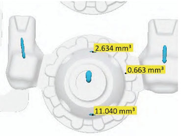
The simulation results of shrinkage and loosening defects show that the shrinkage at the pin hole position is 2.6 mm3 and 11.0 mm3, the shrinkage at the flange position is 0.7 mm3, and the shrinkage at the blocked shaft head position can be machined out at the core. To achieve zero simulation of internal shrinkage defects, continuous improvement will be made to the plan. Rotate the casting by 90 °, and after rotation, there are two of the three protrusions on the casting Near the riser position, and the riser is no longer facing the pin hole position of the casting, but towards the window position. At the same time, the cold needle is cancelled. After adjustment, the simulation results show that there are no shrinkage holes in the pin hole and other positions of the casting, and the shrinkage hole size at the blocked shaft head position is 77.8-80.00 mm3, which can be removed by processing.
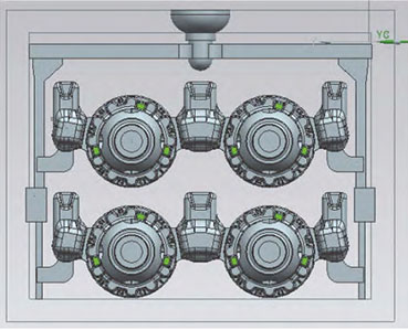
During the trial production process, it was found that the pouring time was long and unstable, requiring 13-16 seconds, which affected the on-site molding production rhythm. Inspect the samples, and ensure that the appearance and dimensions are all qualified. The full mold material and porosity testing are also qualified; 100% X-ray inspection, no internal defects found; The third-party CT testing on the client side was qualified, and process optimization was carried out to address the problems in the trial production: there was a difference of 5-8 seconds between the simulated filling time and the actual pouring time, which affected the production cycle, and the process yield was low, only 36.7%. The analysis is the impact of exhaust. Due to the large volume of sand cores in the differential housing, gas will be generated during the casting process when the sand cores are burned, which will affect the casting time. The new process plan adds exhaust fins to the horizontal runner for exhaust, and separates the bottom of the exhaust fins into separate blocks for use. To improve the yield rate, the two vertical runners were eliminated, and the horizontal runners were reduced in weight. The inner runner was directly fed into the iron from the top of the riser, and the inner runner of the riser was overlapped. A new improved process plan was proposed. The new improved process simulates a pouring and filling time of 8.539 seconds, and the actual pouring and filling time for subsequent production is 10.2~10.3 seconds, which can meet the on-site production pace. By reducing the number of runners and optimizing the pouring system, the process can be improved
The production rate has increased from 36.7% to 42.7%. The main reason for the overall low production rate of the process is that the casting diameter is large and the thickness is thin. In order to meet the requirements of internal defects, risers are added for shrinkage compensation.
Conclusion
During the trial production process, no shrinkage or loosening defects were found in the internal X-ray inspection of the product, Good appearance. The castings have been mass-produced, with 1887 pieces inspected for appearance in a certain month, 62 pieces of waste, with a pass rate of 96.71%. Among them, there are 37 external sand holes,The scrap rate is 1.96%; 18 items were damaged by collision, with a scrap rate of 0.95%; Shot blasting 7 pieces of unclear post cast characters, with a scrap rate of 0.37%; Processing waste on the client side The rate is below 1%, achieving the goal of product development.