
The casting adopts the green sand production process, and the sand core is made of coated sand. The mold plate is arranged as 1 piece / mold. The profile of the casting is shown in Figure 1.

1. Shrinkage
Due to the complex structure of the inner cavity of the valve body, especially the machining allowance of some end faces in the axial direction of the valve stem hole is only 0.5 mm. In this case, it is necessary to ensure the machining allowance of the end face and prevent the reduction of the section of the oil cavity due to the increase of the machining amount, which will affect the oil flow of the oil cavity. Therefore, whether the shrinkage rate selected in the design is consistent with or close to the actual shrinkage rate has a great impact on whether the machining allowance can be guaranteed.
According to the specific requirements of different parts of the inner cavity of the valve body and the characteristics of the coated sand core, and combined with the process characteristics of machining, the method of selecting the shrinkage rate by sections is adopted. Considering the complex structure of the inner cavity of the casting and obvious resistance to shrinkage, within the size of 120 mm shown in Figure 1, the shrinkage rate in the axial direction of the valve stem hole is taken as 0.3%, and the shrinkage rate in other parts is taken as 0.6%.
2. Pouring and riser system
The open gating system is selected, the section ratio of each unit is within F: F Cross: F straight = 1.4:1.2:1, the number of feeding risers is 2, and the positions are selected at B and C as shown in Figure 1, which can make the temperature field distribution of the mold more balanced and conducive to the uniformity of linear shrinkage of the casting.
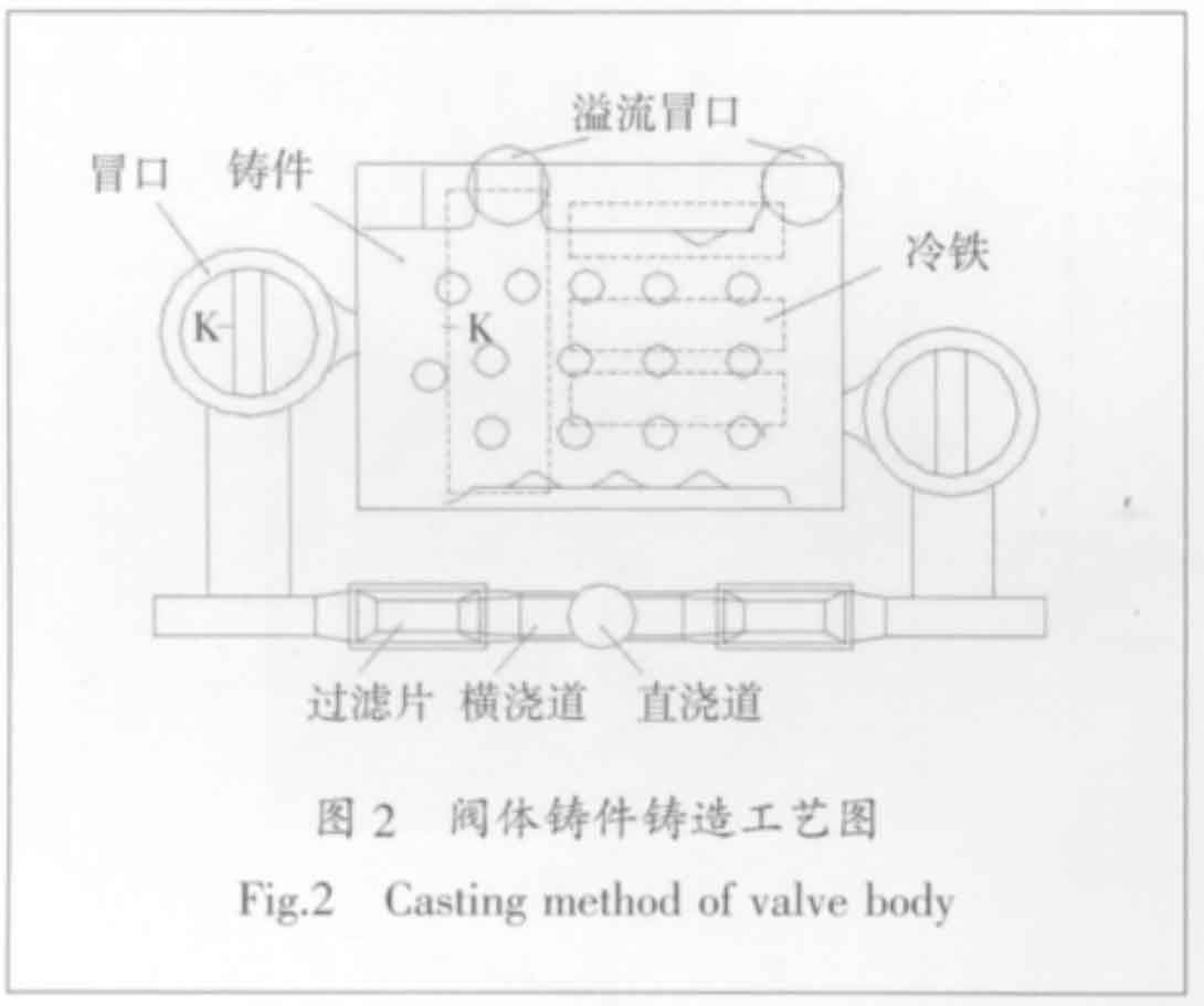
As the finished parts of the valve body must bear high pressure during operation, the casting shall not have any shrinkage cavity or porosity defects on the surface of the machined hole and its adjacent area, so as to prevent leakage and pressure relief and affect the performance of the hydraulic control system. Therefore, the feeding process of top riser and cold iron is adopted. Riser size is φ 130mm × 180 mm (height), the casting process is shown in Figure 2.
3. Sand core
Because there are many oil passages in the inner cavity of the valve body, and most of them are in the shape of deep flat cavity, there are two difficulties in the manufacture of the sand core of the valve body: first, the filling of the main core of the valve hole is not easy to be dense; Second, the number of interfaces between the auxiliary core and the main core is large, the operation space is small, and it is inconvenient to repair. If there is sand sticking, burr or even seam in the inner cavity of the casting, it will also cause great difficulties to the cleaning process. In order to solve these problems, not only the manufacturing quality of the core box mold is highly excellent, but also the coated sand selected should have high strength and good fluidity, so as to ensure the integrity and compactness of the sand core; In addition, the low change of phase transformation volume and excellent collapsing performance make the inner cavity of the casting smooth and burr free.
Based on the above requirements, NFS cer90 coated sand with artificial sand content of 50% ~ 90% is selected to prepare valve body sand core; The sand core coating is HA type coating.
4. Modeling
The sand core of the valve body is complex, and there are many sand cores assembled, with a total of more than 20 kinds and more than 30 pieces. In the pouring process, not only the resin of the coated sand itself will produce a large amount of gas, but also the binder used for sand core assembly will produce a large amount of gas. Because the sand core assembly is a semi closed shell, it is more difficult to discharge the gas from the cavity. In order to discharge gas quickly, the design process of quick gas discharge from overflow riser is adopted. During modeling, the overflow riser is drilled through. KW molding production line in Germany is adopted for molding, and the size of sand box is 800 mm × 600 mm × 300 / 300 mm。
5. Smelting
The chemical composition design is shown in the table.
| Element | C | Si | Mn | Sn | S | P |
| w(B %) | 3.85-3.95 | 2.45-2.65 | 0.35-0.45 | 0.020-0.030 | ≤0.02 | ≤0.05 |
Raw materials are: Q10 pig iron, scrap steel at profile corners, 65 ferromanganese; T-1 spheroidizing agent, 75 ferrosilicon inoculant and calcium barium inoculant. The melting process of 3 T / h medium frequency induction furnace, high temperature discharge and multiple inoculation in the ladle is adopted. The discharging temperature of molten iron is 1 480 ~ 1 500 ℃. Three times of inoculation in the ladle: inoculation at the bottom of the ladle, inoculation in the ladle (added after 2 / 3 of the molten iron in the later stage of the spheroidization reaction), inoculation on the cladding surface (added after the spheroidization treatment and slag removal). The dosage of inoculant is 0.25%, 0.35% and 0.3% respectively. The test block used for testing performance is single cast Y-type (the standard thickness in GB / t1348-2009 is 25mm).
6. Pouring
The pouring process parameters selected in the design are: pouring temperature 1 390 ~ 1 320 ℃; The total mass of molten iron in the mold is 142 kg, the pouring time can be calculated according to the empirical formula, t = 17.5 s, and the design control range is 17 ~ 21 s. In order to ensure the spheroidizing quality and prevent inoculation recession, instantaneous inoculation is carried out during pouring. The amount of inoculant is 0.1% and the inoculation time is 14 ~ 18 s.