
In my extensive experience with the production of centrifugal ductile iron pipes using hot mold processes, I have frequently encountered persistent quality issues related to slag inclusion defect and porosity, particularly at the socket D3 position of large-diameter pipes (with diameters ≥ 1000 mm). These defects significantly compromise the aesthetic appearance and mechanical strength of the final products, leading to increased rejection rates and economic losses. Through systematic investigation and process optimization, I have identified key contributing factors and developed effective preventive strategies. This article delves into a comprehensive analysis of the slag inclusion defect formation mechanisms, incorporating experimental data, mathematical models, and practical insights to provide a thorough understanding and actionable solutions.
The centrifugal casting process for ductile iron pipes involves pouring molten iron into a high-speed rotating mold, where centrifugal force facilitates distribution and solidification. However, the socket region, especially the D3 face, is prone to slag inclusion defect and porosity due to its thicker cross-section and slower cooling rates. These defects manifest as surface irregularities, internal voids, and reduced density, adversely affecting pressure integrity and corrosion resistance. The primary challenge lies in managing impurities within the molten iron and controlling solidification dynamics to minimize defect formation.
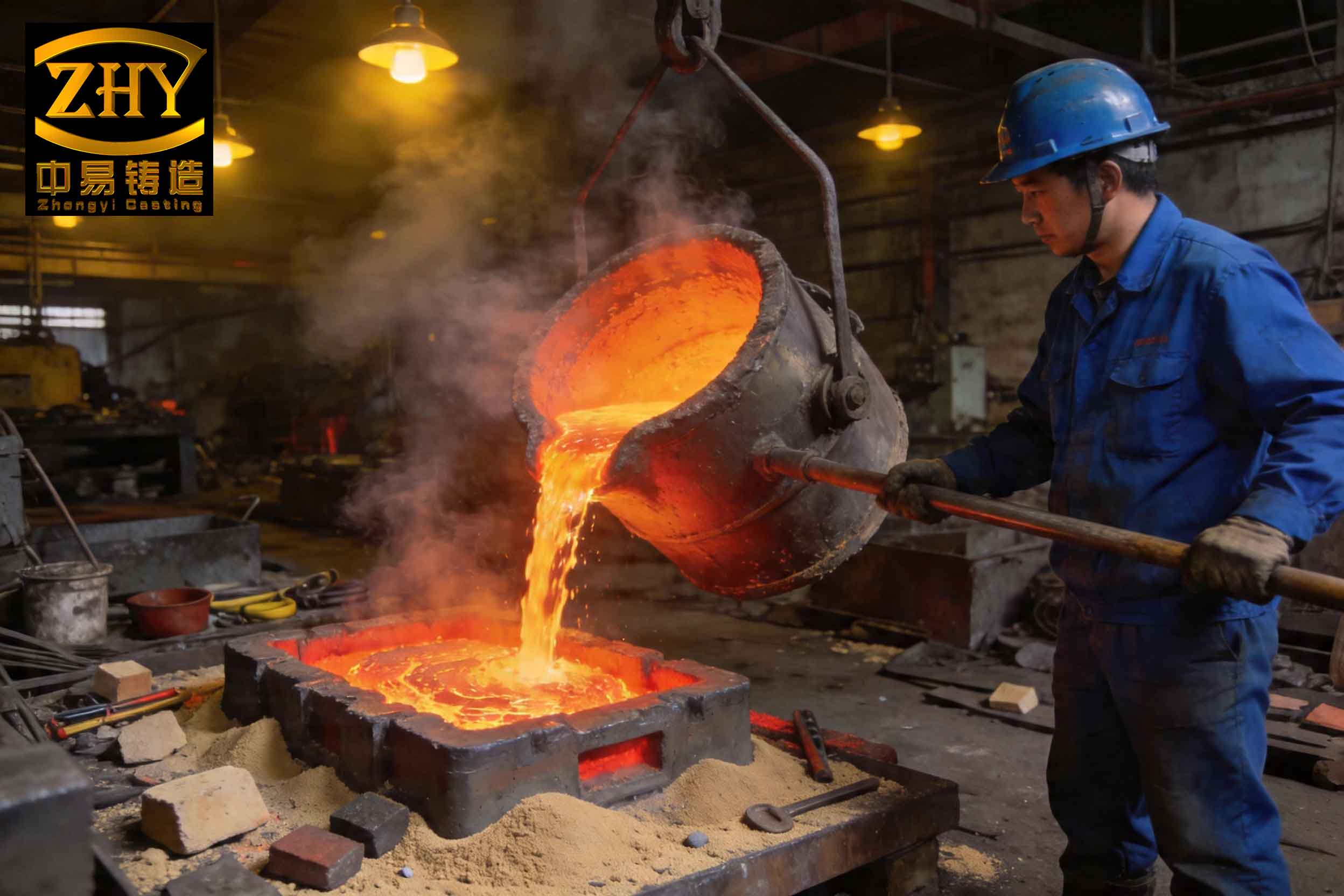
To quantify the severity of the slag inclusion defect, I typically measure two critical parameters: the average thickness of the slag layer at the D3 face and the density ratio (often termed “致密度” in the original context, but here referred to as relative density). The slag layer thickness is assessed by cutting samples from three random locations on the D3 face, each approximately 18 mm deep, and using a vernier caliper to measure the visibly distinct slag-porosity zone. The average of these measurements provides the slag layer thickness. For density evaluation, cubic samples of about 5 mm edge length are extracted from similar locations. The mass \( M \) is measured, and the volume \( V \) is determined via water displacement after coating with a thin layer of rosin to seal surface pores. The actual density \( \rho_{\text{actual}} \) is calculated as:
$$ \rho_{\text{actual}} = \frac{M}{V} $$
The relative density \( \rho_{\text{relative}} \) is then derived by comparing this to the theoretical density of ductile iron \( \rho_{\text{theoretical}} \), typically around 7.1 g/cm³:
$$ \rho_{\text{relative}} = \frac{\rho_{\text{actual}}}{\rho_{\text{theoretical}}} \times 100\% $$
In my observations, untreated cases exhibit an average slag layer thickness of 10 mm and a relative density of merely 58%, highlighting the critical need for intervention. The formation of slag inclusion defect is intrinsically linked to the presence of non-metallic inclusions, such as oxides, sulfides, and carbides, which originate from various sources including inherent melt impurities, oxidation during processing, and coating debris. Under centrifugal force, these low-density inclusions migrate inward toward the rotational axis, accumulating at the D3 face where solidification is delayed, thus forming a porous, slag-rich layer.
A fundamental factor influencing the propensity for slag inclusion defect is the chemical composition of the molten iron. Specifically, residual magnesium (Mg) and titanium (Ti) levels play pivotal roles. Magnesium, while essential for nodularization, is highly reactive and readily oxidizes to form a viscous oxide film on the melt surface. This film, often in a semi-solid state, is difficult to remove completely during slag skimming and can fragment, entrapping sulfur compounds and entering the melt. My trials indicate that when residual Mg exceeds 0.06%, the incidence of slag inclusion defect rises markedly. Therefore, I maintain residual Mg within 0.040–0.060% to balance nodularization efficacy with oxidation minimization. Titanium, primarily introduced via pig iron, tends to form high-melting-point compounds like TiC, TiN, and TiO. At concentrations above 0.050%, these compounds increase melt viscosity, impair slag separation, and exacerbate inclusion entrapment. Hence, I restrict Ti to below 0.050%. The optimal composition ranges I recommend are summarized in Table 1.
| Element | Electric Furnace Melt (%) | Nodularized Melt (%) |
|---|---|---|
| Carbon (C) | 3.5–3.7 | 3.4–3.6 |
| Silicon (Si) | 0.8–1.0 | 2.0–2.2 |
| Manganese (Mn) | 0.2–0.3 | 0.2–0.3 |
| Phosphorus (P) | 0.070–0.080 | < 0.07 |
| Sulfur (S) | 0.020–0.030 | < 0.010 |
| Residual Mg | – | 0.050–0.070 |
| Titanium (Ti) | < 0.050 | < 0.050 |
| Carbon Equivalent (CE) | 4.25–4.35 | 4.25–4.35 |
Beyond composition, melt treatment practices profoundly affect slag inclusion defect formation. I conducted experiments using a 15-ton electric furnace (3000 kW power) to evaluate the impact of superheating temperature and holding time on slag removal efficiency. The furnace was operated at a heating power of 2200 kW until reaching target temperatures, followed by holding at 500 kW for specified durations. The results, presented in Table 2, demonstrate that both higher superheating temperatures and extended holding periods enhance slag separation, reducing slag inclusion defect severity. At 1480°C with a 10-minute hold, slag removal increased to 0.32 tons per heat, correlating with improved D3 face quality. This underscores the importance of adequate thermal energy and time for inclusions to coalesce and float out.
| Superheating Temperature (°C) | Holding Time (min) | Slag Removal (tons) | Average Slag Layer Thickness (mm) | Average Relative Density (%) |
|---|---|---|---|---|
| 1400 | 0 | 0.10 | 8.42 | 60.54 |
| 1400 | 5 | 0.12 | 7.51 | 65.23 |
| 1400 | 10 | 0.21 | 7.22 | 66.52 |
| 1480 | 10 | 0.32 | 5.35 | 69.58 |
The pouring system design is another critical avenue for controlling slag inclusion defect. In centrifugal casting, molten iron is delivered via a ladle, trough, and spout assembly that traverses along the rotating mold. Key variables include pouring position, socket filling time, and flow characteristics. I performed trials with a consistent melt composition (as per Table 1) and treatment (1480°C superheat, 10-minute hold, pouring temperature 1320–1350°C) to isolate these effects. The pouring position, defined as the distance from the mold end where iron enters, influences filling pressure and turbulence. As shown in Table 3, a position of 0 mm (direct entry) yields the lowest slag layer thickness and highest relative density, attributable to maximal filling pressure and minimized reoxidation. Conversely, positions at 50 mm or 100 mm exacerbate slag inclusion defect due to reduced pressure and increased splash. Socket filling time, adjusted by ladle tilting speed, also shows a minor influence; shorter times (3 s) slightly improve density over longer times (5 s). Furthermore, smooth, non-turbulent flow in the trough and spout is paramount. Turbulent flow causes excessive oxidation and scours coating materials into the melt, directly contributing to slag inclusion defect. Optimizing trough geometry and coating adherence ensures laminar flow, significantly reducing inclusions.
| Pouring Position (mm) | Socket Filling Time (s) | Flow Character | Average Slag Layer Thickness (mm) | Average Relative Density (%) |
|---|---|---|---|---|
| 0 | 3 | Turbulent | 5.11 | 78.99 |
| 50 | 3 | Turbulent | 6.15 | 66.87 |
| 100 | 3 | Turbulent | 7.63 | 60.21 |
| 0 | 5 | Turbulent | 6.05 | 75.75 |
| 50 | 5 | Turbulent | 7.28 | 65.25 |
| 100 | 5 | Turbulent | 7.89 | 59.23 |
| 0 | 3 | Smooth | 4.52 | 85.22 |
| 50 | 3 | Smooth | 6.13 | 69.28 |
| 100 | 3 | Smooth | 6.95 | 65.52 |
| 0 | 5 | Smooth | 4.56 | 79.22 |
| 50 | 5 | Smooth | 6.21 | 68.42 |
| 100 | 5 | Smooth | 6.98 | 62.33 |
Cooling rate during solidification is a dominant factor in mitigating slag inclusion defect. Faster cooling reduces the time available for inclusions to migrate and accumulate, thereby diminishing porosity. The cooling rate is governed primarily by mold coating thickness and cooling water intensity. I measured the temperature decay of molten iron in the socket region using a high-temperature pyrometer to compute average cooling rates. As delineated in Table 4, reducing the insulating coating thickness from 1.0 mm to 0.6 mm and increasing spray water intensity from 30–37 L/(min·m²) to 37–45 L/(min·m²) elevates the cooling rate from 2.22°C/s to 4.12°C/s. This enhancement drastically reduces slag layer thickness to 2.96 mm and boosts relative density to 88.93%. However, excessive cooling can induce chill carbides on the pipe exterior, so I recommend a balanced approach with coating thickness around 0.6 mm and water intensity of 37–45 L/(min·m²). The relationship between cooling rate \( R_c \) and defect severity can be approximated by an empirical equation:
$$ \text{Slag Layer Thickness} = k_1 \cdot e^{-k_2 \cdot R_c} $$
where \( k_1 \) and \( k_2 \) are material-specific constants derived from regression analysis of experimental data. This exponential decay model underscores the profound benefit of accelerated solidification in suppressing slag inclusion defect.
| Mold Coating Thickness (mm) | Spray Water Intensity (L/(min·m²)) | Average Cooling Rate (°C/s) | Average Slag Layer Thickness (mm) | Average Relative Density (%) |
|---|---|---|---|---|
| 1.0 | 30–37 | 2.22 | 6.12 | 68.23 |
| 0.9 | 30–37 | 2.58 | 5.25 | 71.56 |
| 0.8 | 37–45 | 3.25 | 4.23 | 75.12 |
| 0.7 | 37–45 | 3.56 | 3.56 | 78.12 |
| 0.6 | 37–45 | 4.12 | 2.96 | 88.93 |
Mechanical sources of inclusions also contribute significantly to slag inclusion defect. These include flaking of mold coatings, spalling of trough linings, and inadequate drying of core washes. To address these, I emphasize using high-strength, adherent coatings for both molds and troughs. The coating should withstand thermal shock without cracking or detaching. Additionally, core washes must be thoroughly dried to prevent steam generation and coating disintegration during pouring, which can introduce particulate matter into the melt. Implementing rigorous quality checks for coating application—ensuring proper spraying pressure and thickness uniformity—further minimizes mechanical slag inclusion defect.
Based on my findings, I have consolidated an optimized process protocol that effectively prevents slag inclusion defect in hot mold centrifugal ductile iron pipe sockets. This protocol integrates compositional control, refined melting practices, precise pouring parameters, and enhanced cooling, as summarized below:
- Chemical Composition: Maintain C: 3.4–3.6%, Si: 2.0–2.2%, Mn: 0.2–0.3%, P < 0.07%, S < 0.010%, residual Mg: 0.050–0.070%, Ti < 0.050%, and CE: 4.25–4.35%.
- Melt Treatment: Superheat to 1480°C, hold for 10 minutes to promote slag separation, and pour at 1330–1350°C.
- Pouring System: Set pouring position at 0 mm, socket filling time to 3 seconds, and ensure smooth, non-turbulent flow in troughs and spouts.
- Cooling Regime: Apply mold coating thickness of 0.6 mm and spray water intensity of 37–45 L/(min·m²) to achieve an average cooling rate of approximately 4.12°C/s.
- Coating Management: Use high-strength coatings for molds and troughs, verify adhesion, and ensure core washes are completely dry before casting.
Adopting this optimized protocol has yielded remarkable improvements. The slag inclusion defect at the D3 face is now consistently controlled, with slag layer thickness ranging from 0 to 2.5 mm and relative density exceeding 91%. The socket surface appears smooth and dense, meeting stringent quality standards. This holistic approach not only addresses the immediate slag inclusion defect but also enhances overall production efficiency and product reliability.
In conclusion, the formation of slag inclusion defect and porosity in hot mold centrifugal ductile iron pipe sockets is a multifactorial problem rooted in melt purity, processing dynamics, and solidification behavior. Through meticulous analysis of factors such as chemical composition, slag removal efficiency, pouring system design, and cooling rate, I have demonstrated that targeted interventions can substantially mitigate these defects. The integration of robust melt practices, optimized pouring parameters, and accelerated cooling forms a synergistic strategy to eliminate slag inclusion defect. Continuous monitoring and adaptation of these parameters are essential for sustaining high-quality production. Future work could explore advanced filtration techniques or real-time process control systems to further reduce inclusion levels. Ultimately, understanding and controlling the intricate interplay of these variables is key to manufacturing superior ductile iron pipes free from debilitating slag inclusion defect.