
In my work on investment casting for aerospace and energy components, I have repeatedly seen that the ceramic shell is not a passive container but an active participant in the thermal and mechanical history of the casting. The shell must survive dewaxing, high-temperature sintering, metal pouring, solidification, and cooling. When the shell fails, the casting fails. When the shell distorts, dimensional accuracy is lost. When the shell cracks, the defect is often impossible to repair. For this reason, I treat thermal stress control in ceramic shells as a central engineering problem, not a secondary process detail. I also study related net-shape processes such as evaporative pattern casting, because evaporative pattern casting and investment casting share many thermal-management principles even though their pattern removal mechanisms differ. In evaporative pattern casting, a polymer pattern is vaporized by the molten metal, whereas in investment casting the pattern is removed before pouring. That difference changes the timing and location of thermal load, but the underlying stress physics remains comparable. I therefore compare lessons from evaporative pattern casting with ceramic shell practice whenever I need to explain why uniform heating, controlled phase change, and matched thermal expansion are so important.
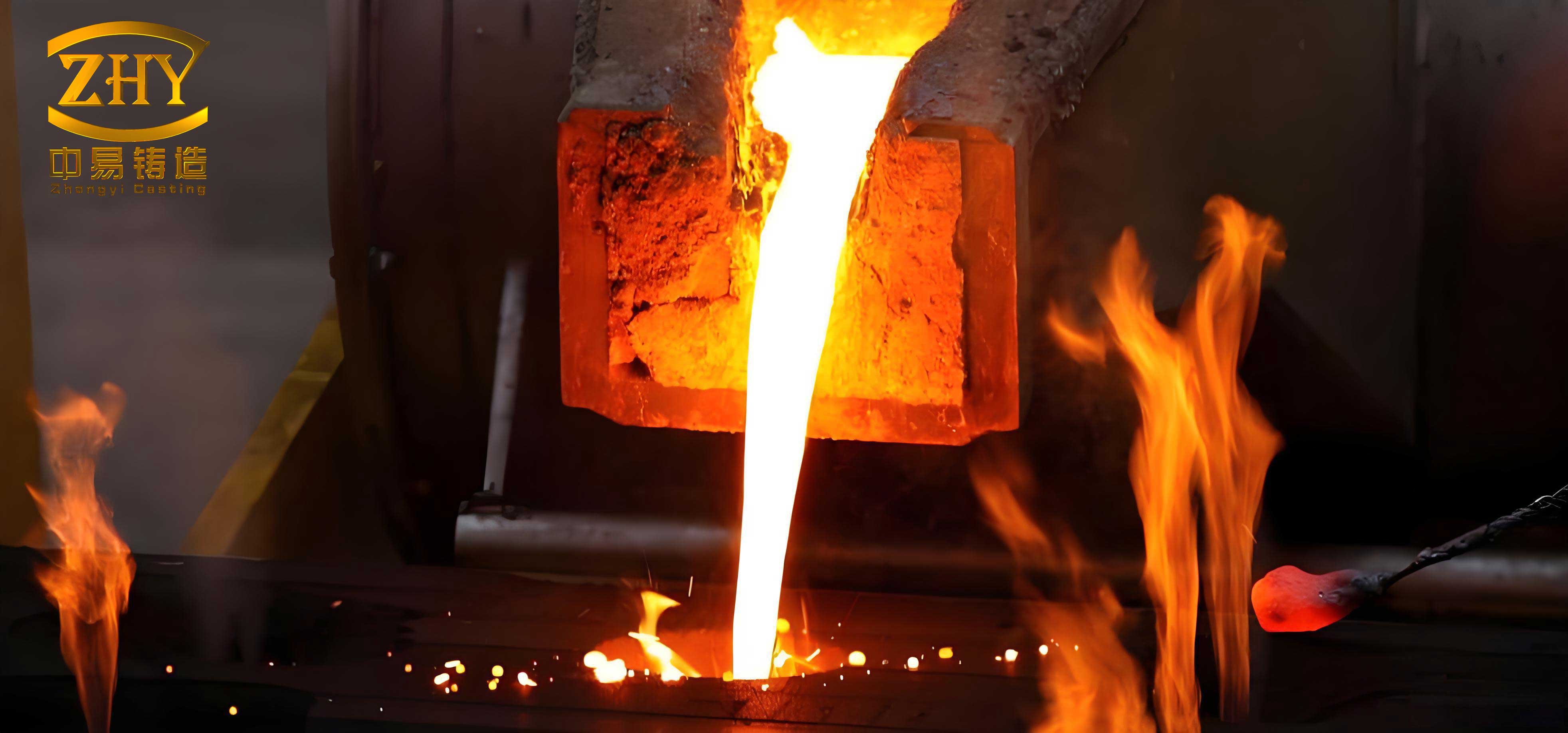
My central observation is simple: thermal stress in a ceramic shell arises because different regions of the shell want to change volume by different amounts at different times. If the shell is restrained, if the temperature field is steep, or if the material cannot accommodate strain, stress rises. Once the local stress exceeds the tensile strength of the ceramic, cracking begins. If the stress remains below fracture but above the elastic limit of the binder network, deformation and warpage accumulate. In my experience, the most successful programs combine four actions: they optimize the material system, regulate the process parameters, redesign the shell structure, and introduce simulation and intelligent control. I have seen each action reduce defects, but the strongest results come from integrating all four.
The first principle I use is the thermoelastic stress relation. For a constrained isotropic body, the first-order thermal stress can be expressed as:
$$ \sigma = \frac{E \alpha \Delta T}{1-\nu} $$
Here, \(\sigma\) is thermal stress, \(E\) is elastic modulus, \(\alpha\) is the coefficient of thermal expansion, \(\Delta T\) is the temperature difference relative to a stress-free reference state, and \(\nu\) is Poisson’s ratio. This equation tells me that stress rises with stiffness, expansion mismatch, and temperature difference. In ceramic shells, all three terms are significant. The shell is stiff, the ceramic expands, and the temperature difference during dewaxing or pouring can be hundreds of degrees. I have found that even a modest reduction in \(\alpha\) or \(E\) can produce a disproportionate improvement in crack resistance. The same logic appears in evaporative pattern casting, where the pattern and coating must tolerate rapid thermal decomposition and gas evolution. Although evaporative pattern casting does not use a ceramic shell in the same way, the need to manage expansion and thermal gradients is equally real.
The second principle is transient heat conduction. The temperature field inside the shell is governed by:
$$ \rho c_p \frac{\partial T}{\partial t} = \nabla \cdot (k \nabla T) + Q $$
In this equation, \(\rho\) is density, \(c_p\) is specific heat capacity, \(T\) is temperature, \(t\) is time, \(k\) is thermal conductivity, and \(Q\) is any internal heat source or sink. For ceramic shells, \(k\) is usually low. That low conductivity preserves a temperature gradient, and the gradient drives thermal strain mismatch. I often explain this to process engineers by saying that the shell is not heated uniformly; it is heated from one side, and the other side resists. In evaporative pattern casting, the pattern decomposition also creates a moving thermal front and gas pressure, so the local heat transfer is even more complex. But in both evaporative pattern casting and investment casting, the practical goal is the same: reduce the magnitude and duration of the temperature gradient.
The third principle is interface heat transfer. During pouring, the heat flux between metal and shell can be written as:
$$ q = h_i A (T_m – T_s) $$
Here, \(q\) is heat flow rate, \(h_i\) is the interfacial heat transfer coefficient, \(A\) is contact area, \(T_m\) is metal temperature, and \(T_s\) is shell temperature. I have measured and modeled this term many times. When the metal first touches the shell, \(h_i\) can change rapidly because of contact resistance, gap formation, and surface reaction. A high \(h_i\) creates a sharp thermal shock. A low \(h_i\) reduces shock but may slow solidification and alter grain structure. In evaporative pattern casting, the decomposing pattern produces gas that can alter contact and heat transfer, which is another reason I keep evaporative pattern casting in mind when I design thermal experiments for investment casting.
The fourth principle is the equivalent conductivity of a multilayer shell. Because most ceramic shells have a face coat, a transition coat, and a backup coat, I calculate an effective conductivity:
$$ \lambda_e = \frac{L_t}{\sum_i \frac{L_i}{\lambda_i}} $$
In this expression, \(L_t\) is total shell thickness, \(L_i\) is the thickness of layer \(i\), and \(\lambda_i\) is the thermal conductivity of layer \(i\). This simple rule helps me decide whether a change in face-coat material will dominate the thermal response or whether the backup layer controls the gradient. It also helps me compare an investment casting shell with an evaporative pattern casting coating system, because both can be represented as layered thermal resistances.
The fifth principle is fracture initiation. I use linear elastic fracture mechanics as a screening tool:
$$ K_I = Y \sigma \sqrt{\pi a} $$
Here, \(K_I\) is the mode I stress intensity factor, \(Y\) is a geometry factor, \(\sigma\) is applied stress, and \(a\) is crack size. When \(K_I\) reaches the fracture toughness \(K_{IC}\), crack growth becomes likely. This equation reminds me that a small defect in a high-stress region is more dangerous than a large defect in a low-stress region. In my shell designs, I therefore focus on corners, thickness transitions, and gate-contact zones. I also use Weibull statistics to estimate failure probability:
$$ P_f = 1 – \exp\left[-\int_V \left(\frac{\sigma}{\sigma_0}\right)^m dV\right] $$
Here, \(P_f\) is failure probability, \(V\) is volume, \(\sigma_0\) is a scale parameter, and \(m\) is the Weibull modulus. A low \(m\) means wide scatter and high risk. Ceramic shells often have low Weibull modulus, which is why I prefer robust process windows rather than narrow optimum points. I have seen the same need in evaporative pattern casting, where coating variability and gas defects can create scatter in final quality.
Mechanisms during dewaxing. In my experience, dewaxing is the most underappreciated stage. The pattern expands before it melts, and the shell is still green, weak, and full of binder. If the wax or polymer expands against a constrained shell, pressure rises and cracks form. The classical steam dewaxing route heats the outside first, so the pattern surface can soften while the interior remains solid. That sequence is unfavorable. I have seen internal pressure spikes that exceed the green strength of the shell. In evaporative pattern casting, the pattern is not removed before pouring, but the polymer still decomposes and generates gas pressure. That similarity is why I often tell teams that evaporative pattern casting and investment casting both require controlled phase change, just at different times.
Mechanisms during sintering. Sintering removes volatiles, burns out organics, and develops ceramic bonding. I divide the furnace cycle into at least three zones: low-temperature decomposition, intermediate binder burnout, and high-temperature sintering. In the low-temperature zone, gas evolution must not outrun diffusion through the shell. If heating is too fast, internal pressure creates blisters and laminations. In the intermediate zone, the binder network changes and the shell can become weak. In the high-temperature zone, shrinkage and densification create new stresses. I have found that a slow ramp between 200 °C and 600 °C is especially important. In evaporative pattern casting, a similar principle applies to coating drying and pattern decomposition, because rapid gas generation can damage the mold surface.
Mechanisms during pouring and solidification. The metal entering the shell creates the largest thermal shock. The inner surface expands, the outer surface lags, and a tensile stress develops at the cooler surface. For directional solidification, the shell also sees a moving temperature gradient. If the gradient is too steep, the shell can crack. If it is too shallow, grain selection and dendrite growth suffer. I have used the following simplified energy balance for solidification:
$$ \rho_s L_f \frac{\partial f_s}{\partial t} = \nabla \cdot (k \nabla T) $$
Here, \(\rho_s\) is solid density, \(L_f\) is latent heat of fusion, and \(f_s\) is solid fraction. This equation couples the casting to the shell. The shell controls heat extraction, and heat extraction controls solidification. In evaporative pattern casting, the decomposing pattern also absorbs heat and produces gas, so the thermal balance includes additional terms. I mention evaporative pattern casting here because it shows that any net-shape process must respect the same conservation laws.
Factors I track most closely. I group the influencing factors into material factors, process factors, and geometry factors. I have summarized them in Table 1. The table is not merely a list; it is my daily checklist when a shell cracks or a casting distorts.
| Factor | Mechanism | Control direction | My practical indicator |
|---|---|---|---|
| Coefficient of thermal expansion, \(\alpha\) | Higher \(\alpha\) increases thermal strain and stress | Select low-\(\alpha\) face materials such as zircon | Measured dilatometry curve from 20 °C to 1400 °C |
| Thermal conductivity, \(\lambda\) | Lower \(\lambda\) increases temperature gradient | Improve conductivity without losing refractoriness | Effective shell conductivity \(\lambda_e\) |
| Elastic modulus, \(E\) | Higher \(E\) means higher stress at fixed strain | Reduce stiffness while maintaining strength | Three-point bending modulus before and after sintering |
| Dewaxing rate | Fast heating causes pattern expansion against green shell | Use microwave or controlled ramp | Peak internal pressure and shell strain |
| Shell preheat | Low preheat increases thermal shock | Match preheat to pouring temperature | Interfacial temperature difference |
| Wall thickness uniformity | Nonuniform cooling creates bending stress | Design uniform sections and fillets | Thickness map and cooling rate map |
| Corner radius | Sharp corners concentrate stress | Use generous fillets | Stress concentration factor \(K_t\) |
| Binder chemistry | Binder controls green strength and creep | Optimize silica sol or ethyl silicate system | Green strength and sintered strength |
| Reinforcement | Fibers add strength and conductivity | Use carbon fiber or hybrid reinforcement | Thickness reduction and crack density |
| Atmosphere and burnout | Incomplete burnout creates gas pressure | Control airflow and heating rate | Residual carbon and off-gas profile |
Material optimization. I begin material optimization by refusing to treat the shell as a single material. A real shell is a graded composite. The face coat must resist chemical attack from the molten alloy. The transition layer must buffer expansion mismatch. The backup layer must provide mechanical strength and thermal stability. I have found that zircon, alumina, mullite, and high-alumina bauxite each have a place, but the placement matters more than the individual choice. Table 2 summarizes the thermal and mechanical properties I use for preliminary screening. I update this table whenever I test a new supplier or a new particle-size distribution.
| Material | CTE, \(10^{-6}/^\circ C\) | Thermal conductivity, W/(m K) | Bending strength, MPa | My typical use |
|---|---|---|---|---|
| Zircon, ZrSiO\(_4\) | 4.5–5.5 | 1.5–3.0 | 30–50 | Face coat for reactive alloys |
| Fused alumina, Al\(_2\)O\(_3\) | 7.0–8.5 | 5.0–8.0 | 50–80 | Face or transition layer |
| Mullite, 3Al\(_2\)O\(_3\)·2SiO\(_2\) | 5.0–6.0 | 3.0–6.0 | 40–60 | Transition layer |
| High-alumina bauxite | 6.0–7.5 | 2.0–4.0 | 25–45 | Backup layer |
| Carbon fiber reinforcement | Axial negative to near zero | \(\geq 100\) | \(\geq 3500\) fiber tensile | Outer structural layer |
| Yttria-stabilized additive | Depends on matrix | Depends on matrix | Improves toughness | 1–2% addition for crack arrest |
Slurry formulation. I treat slurry formulation as a rheology problem coupled to a strength problem. The powder-to-binder ratio is the first variable. If the ratio is too high, the slurry becomes viscous and hard to coat uniformly. If it is too low, the green body shrinks too much and lacks strength. I normally target a powder-to-binder ratio between 2.0:1 and 2.9:1, but I refine that range for each particle-size distribution. The following relation helps me describe the solid loading:
$$ \phi_s = \frac{V_p}{V_p + V_b} $$
Here, \(\phi_s\) is solid volume fraction, \(V_p\) is particle volume, and \(V_b\) is binder volume. Higher \(\phi_s\) increases green strength and reduces shrinkage, but it also raises viscosity. I use a modified Krieger–Dougherty form to estimate viscosity:
$$ \eta = \eta_0 \left(1 – \frac{\phi_s}{\phi_{\max}}\right)^{-[\eta] \phi_{\max}} $$
In this equation, \(\eta\) is apparent viscosity, \(\eta_0\) is carrier viscosity, \(\phi_{\max}\) is maximum packing fraction, and \([\eta]\) is intrinsic viscosity. This model explains why a small change in solid loading can cause a large change in coatability. I have applied the same logic to evaporative pattern casting coatings, where coating viscosity controls gas permeability and surface finish. In both investment casting and evaporative pattern casting, the formulation window is narrower than many people expect.
Reinforcement and thickness reduction. When I need to reduce shell thickness without losing strength, I consider carbon fiber reinforcement. The fiber has high tensile strength and high thermal conductivity, so it can carry load and spread heat. I have used carbon fiber cloth wound or laminated into the outer shell. The result is often a shell that is 5–7 mm thick instead of 8–10 mm. The thinner shell heats and cools faster, which can reduce the temperature gradient. However, I must be careful: the fiber must not contact the molten metal, and the interface between fiber and ceramic must survive thermal cycling. I have summarized the reinforcement trade-offs in Table 3.
| Reinforcement strategy | Benefit | Risk | My control action |
|---|---|---|---|
| Short carbon fibers in backup slurry | Distributed crack bridging | Poor dispersion and weak zones | Control mixing time and surfactant |
| Carbon fiber cloth outer wrap | High strength and thermal spreading | Interlayer delamination | Optimize slurry wetting and layup |
| Hybrid ceramic fiber | Better oxidation resistance | Lower conductivity than carbon | Balance strength and heat transfer |
| Thickness reduction | Lower thermal mass and faster response | Reduced buckling resistance | Add local ribs where needed |
| Graded fiber content | Matches stress distribution | Complex manufacturing | Use simulation to place fibers |
Dewaxing process optimization. I have evaluated several dewaxing routes. Traditional steam dewaxing is fast and inexpensive, but it creates a large thermal gradient and high internal pressure. Microwave dewaxing heats the pattern more selectively and can reduce the peak stress. A typical microwave cycle I have seen effective is 275 °C for 30 min, but I adjust this based on pattern size and shell thickness. Reverse solidification path dewaxing, which I abbreviate as RSPD, controls the heating direction so the pattern melts from the inside outward. That approach reduces the pressure against the shell and raises success rate. Modified heating path method, or MTHM, slows the ramp in the critical expansion window. I have used all three approaches. Table 4 compares them from my perspective.
| Dewaxing route | Advantage | Limitation | Where I apply it |
|---|---|---|---|
| Steam dewaxing | High productivity, low cost, simple equipment | High thermal stress, cracking risk, difficult precision control | Thick, simple parts with forgiving geometry |
| Microwave dewaxing | Lower peak stress, uniform heating, high efficiency | Higher equipment investment, composition sensitivity | Thin-wall complex parts and high-value castings |
| Reverse solidification path dewaxing | Low stress concentration, success rate above 95% | Complex control and precise instrumentation | Aerospace blades and directionally solidified parts |
| Modified heating path method | Reduces peak stress in existing steam furnaces | Limited productivity gain | Retrofit of existing dewaxing equipment |
| Hybrid microwave plus ramp control | Balances stress and cycle time | Requires recipe development | Mixed production of thin and thick shells |
Sintering and pouring control. I use staged sintering because a single ramp cannot satisfy all chemical and physical requirements. I hold between 200 °C and 800 °C to decompose organics, then raise the temperature to 1300–1500 °C for ceramic bonding. In the organic decomposition window, I keep the heating rate between 2 °C/min and 5 °C/min. If I go faster, gas pressure can exceed the strength of the shell. The following empirical relation helps me estimate gas pressure:
$$ P_g = \frac{nRT}{V} $$
Here, \(P_g\) is gas pressure, \(n\) is moles of gas, \(R\) is the gas constant, \(T\) is temperature, and \(V\) is available pore volume. This equation is simple, but it explains why burnout cracks form when the shell is sealed or when the heating rate is too high. In evaporative pattern casting, gas pressure is even more central because the pattern decomposition produces gas directly in the mold. I often compare burnout control in investment casting with gas removal in evaporative pattern casting, because both require pathways for gas escape.
Pouring and preheat matching. I have found that shell preheat is one of the most powerful levers for reducing thermal shock. A preheat between 1000 °C and 1200 °C can reduce the interfacial temperature difference and lower thermal stress. However, for thin-wall castings, excessive preheat can slow solidification and cause grain growth or shrinkage defects. I therefore optimize the combination of pouring temperature, shell preheat, and withdrawal rate. For directional solidification, the withdrawal rate is often 3–10 mm/min. A faster rate improves productivity but steepens the thermal gradient. I use the following approximate relation for the thermal gradient:
$$ G = \frac{T_{\text{hot}} – T_{\text{cold}}}{\Delta x} $$
Here, \(G\) is temperature gradient, \(T_{\text{hot}}\) and \(T_{\text{cold}}\) are the boundary temperatures, and \(\Delta x\) is distance. If \(G\) is too high, the shell may crack. If \(G\) is too low, the solidification front becomes unstable. I tune the withdrawal rate until the shell stress and the grain structure both meet specification. I have applied similar reasoning to evaporative pattern casting, where cooling rate affects porosity and surface quality.
Numerical simulation. I use multi-physics simulation to predict temperature, stress, and deformation before I cut metal or build a new shell. The heat equation, the stress equilibrium equation, and the interface heat-transfer equation are solved together. The stress equilibrium I use is:
$$ \nabla \cdot \sigma + f = 0 $$
Here, \(\sigma\) is the stress tensor and \(f\) is body force. The thermal strain is:
$$ \varepsilon^{th} = \alpha (T – T_0) $$
The total strain is the sum of elastic, thermal, and creep strains:
$$ \varepsilon = \varepsilon^{e} + \varepsilon^{th} + \varepsilon^{c} $$
In ceramic shells at high temperature, creep can be important. I therefore include a creep law when the shell is above the binder softening range. A common form is:
$$ \dot{\varepsilon}^{c} = A \sigma^n \exp\left(-\frac{Q}{RT}\right) $$
Here, \(\dot{\varepsilon}^{c}\) is creep strain rate, \(A\) is a material constant, \(n\) is stress exponent, \(Q\) is activation energy, and \(R\) is the gas constant. I have found that including creep improves the prediction of warpage and stress relaxation. The same class of models is useful in evaporative pattern casting, where the coating and sand compact have time-dependent behavior.
Model validation. I never trust a simulation without validation. I use thermocouples embedded in the shell, strain gauges on the outer surface, and post-mortem crack mapping. I compare predicted and measured temperatures at several locations. I calculate the error:
$$ E_T = \frac{1}{N}\sum_{i=1}^{N} |T_i^{\text{sim}} – T_i^{\text{exp}}| $$
Here, \(E_T\) is mean absolute temperature error, \(N\) is number of measurement points, \(T_i^{\text{sim}}\) is simulated temperature, and \(T_i^{\text{exp}}\) is experimental temperature. I aim for errors below 5% in the critical temperature range. For stress, direct measurement is harder, so I use crack location and deformation as indirect validation. I have summarized my simulation workflow in Table 5.
| Simulation step | Input | Output | My validation method |
|---|---|---|---|
| Geometry preparation | Shell thickness map, core shape, gating | Discretized model | Coordinate measurement of built shell |
| Thermal property assignment | \(\lambda(T)\), \(c_p(T)\), \(\rho(T)\) | Temperature-dependent material data | Dilatometry and laser flash tests |
| Heat transfer simulation | Furnace curve, pouring temperature, \(h_i\) | Transient temperature field | Thermocouple data |
| Stress simulation | Thermal field, elastic modulus, creep law | Stress and strain fields | Crack location and distortion |
| Deformation prediction | Boundary constraints, contact conditions | Displacement field | Scanning or coordinate measurement |
| Optimization loop | Process variables and shell design | Improved recipe | Production trial |
Intelligent control and digital twins. I have moved from static recipes to adaptive control. In an intelligent dewaxing system, sensors monitor shell temperature and internal pressure, and the controller adjusts heater power and distribution. In pouring and solidification, sensors monitor shell temperature and cooling rate, and the controller adjusts withdrawal speed or cooling gas flow. The goal is to keep the stress state below a safe threshold. I define a stress index:
$$ S = \frac{\sigma_{\max}}{\sigma_{\text{allow}}} $$
Here, \(S\) is stress index, \(\sigma_{\max}\) is maximum predicted or measured stress, and \(\sigma_{\text{allow}}\) is allowable stress. I aim for \(S < 0.7\) during critical stages. A digital twin extends this idea by maintaining a virtual replica of the shell, furnace, and casting. The twin receives real-time data and updates the model. I have used digital twins to predict the effect of a changed dewaxing ramp before committing to production. In evaporative pattern casting, digital twins are also valuable because pattern decomposition and gas flow are difficult to observe directly. I believe evaporative pattern casting and investment casting will both benefit from the same sensor-driven, model-based control philosophy.
Industrial application: aero-engine blades. I have worked on turbine blades with wall thickness as low as 0.8 mm and many cooling holes. The ceramic shell must be strong enough to resist handling but thin enough to cool quickly. I used carbon fiber reinforcement to reduce shell thickness from about 8 mm to about 5 mm. I used reverse solidification path dewaxing to reduce stress during pattern removal. I used numerical simulation to redistribute thickness, adding material at stress concentrations and reducing it where thermal mass was excessive. The result was a shell thermal stress reduction of more than 35%, a yield improvement from about 65% to about 92%, and dimensional accuracy within CT7. Table 6 shows the improvements I recorded.
| Metric | Before integrated control | After integrated control | My interpretation |
|---|---|---|---|
| Shell thermal stress | Baseline | Reduced by more than 35% | Lower cracking and distortion |
| Casting yield | 65% | 92% | Major economic gain |
| Dimensional accuracy | CT8–CT9 | CT7 | Better fit-up and performance |
| Shell thickness | 8 mm | 5–7 mm | Faster thermal response |
| Dewaxing success | Moderate | Above 95% | REduced rejection |
| Crack density | High | Low | Fewer repair operations |
Industrial application: gas turbine hollow blades. I have also studied large hollow blades with uneven wall thickness. These parts are prone to stray grains, segregation, and shell distortion. I used a controlled-thickness directional solidification shell. I started with a three-dimensional design that made wall thickness as uniform as possible. Then I ran heat-transfer and stress analysis. I increased thickness in regions that cooled too quickly and reduced thickness in regions that cooled too slowly. The goal was uniform axial temperature and minimal circumferential and radial gradients. The stress concentration factor dropped from about 3.2 to about 1.8. Temperature gradient consistency improved by about 40%, and stray grain defects decreased by more than 70%. I have summarized these results in Table 7.
| Parameter | Conventional shell | Controlled-thickness shell | Effect |
|---|---|---|---|
| Stress concentration factor | 3.2 | 1.8 | Lower crack risk |
| Axial temperature uniformity | Poor | Improved | Better grain control |
| Circumferential gradient | High | Low | Less distortion |
| Radial gradient | High | Low | Less thermal shock |
| Stray grain defects | Baseline | Reduced by more than 70% | Higher yield |
| Temperature gradient consistency | Baseline | Improved by 40% | More stable solidification |
My integrated control strategy. I do not rely on a single fix. I combine material, process, structure, and intelligence. Table 8 shows the integrated strategy I use when I need to reduce thermal stress by at least 30%. I have applied this strategy to investment casting, and I have adapted parts of it to evaporative pattern casting. In evaporative pattern casting, the pattern material and coating must be selected together, because gas evolution and heat absorption affect the thermal history. In investment casting, the shell material and dewaxing route must be selected together, because pattern expansion and shell strength interact. The details differ, but the systems approach is the same.
| Control dimension | Action | Expected effect | My key metric |
|---|---|---|---|
| Material system | Use low-CTE face coat, graded transition, reinforced backup | Lower thermal strain and higher toughness | Crack density and flexural strength |
| Slurry formulation | Optimize powder-to-binder ratio 2.0:1–2.9:1 | Better green strength and coatability | Viscosity and green strength |
| Dewaxing | Use microwave or reverse-path dewaxing | Lower peak pressure and stress | Dewaxing success rate |
| Sintering | Use staged burnout with controlled ramp | Less gas pressure and cracking | Burnout defect rate |
| Pouring | Match preheat and pouring temperature | Lower interfacial thermal shock | Interfacial \(\Delta T\) |
| Solidification | Optimize withdrawal rate and cooling | Controlled gradient and grain structure | Grain defect rate |
| Structure | Uniform thickness, fillets, local ribs | Lower stress concentration | \(K_t\) and deformation |
| Simulation | Multi-physics coupling and validation | Predict stress before trial | Temperature error and stress index |
| Intelligent control | Sensor-based adaptive recipes | Real-time stress management | Stress index \(S\) |
| Digital twin | Virtual process replica and optimization | Faster recipe development | Prediction accuracy |
What I have learned from evaporative pattern casting. I have learned from evaporative pattern casting that pattern removal and gas management are not separate from thermal stress control. In evaporative pattern casting, the pattern decomposes in contact with the molten metal, so gas pressure, coating permeability, and heat absorption all interact. In investment casting, the pattern is removed earlier, but the shell still experiences gas evolution during burnout and vaporization during pouring. I have therefore adopted a broader view: thermal stress control is also a transport problem. Heat, gas, and mass must all move through the shell without creating local pressure or temperature spikes. When I discuss evaporative pattern casting with colleagues, I emphasize that the same simulation tools, the same sensor networks, and the same statistical quality methods apply. In my opinion, evaporative pattern casting and investment casting should not be treated as completely separate silos. They share enough physics that cross-learning is valuable.
Practical rules I follow. I keep a short list of rules that I apply whenever I design or troubleshoot a ceramic shell. First, I avoid sharp corners. I use fillets and gradual thickness transitions. Second, I avoid rapid heating in the pattern expansion and binder burnout ranges. Third, I measure thermal properties instead of relying on handbook values. Fourth, I validate every simulation with at least one physical measurement. Fifth, I use the thinnest shell that meets strength and handling requirements, because lower thermal mass usually means lower thermal stress. Sixth, I consider reinforcement only when I can control the fiber–matrix interface. Seventh, I treat evaporative pattern casting as a reminder that gas pressure and thermal gradients are coupled. Eighth, I design for robustness, not for a narrow optimum. Ninth, I monitor production data continuously, because shells change with slurry age, humidity, and particle settling. Tenth, I use digital twins to test changes before they reach the shop floor.
Mathematical summary of my control targets. I often express my targets as inequalities. For example, I want the maximum tensile stress to remain below a fraction of the measured strength:
$$ \sigma_{\max} \leq \frac{\sigma_f}{F_s} $$
Here, \(\sigma_f\) is fracture strength and \(F_s\) is a safety factor. I typically use \(F_s = 1.5\) to \(2.0\) for critical shells. I also want the interfacial heat flux to remain below a threshold that causes thermal shock:
$$ q_{\max} \leq q_{\text{crit}} $$
I estimate \(q_{\text{crit}}\) from thermal shock tests. For dewaxing, I want the internal pressure to remain below the green strength:
$$ P_{\text{wax}} \leq \sigma_{\text{green}} $$
For sintering, I want the gas pressure to remain below the shell strength at the local temperature:
$$ P_g(T) \leq \sigma_{\text{shell}}(T) $$
For solidification, I want the thermal gradient to fall within a process window:
$$ G_{\min} \leq G \leq G_{\max} $$
These inequalities are simple, but they guide my experiments. I use them in design reviews and in simulation optimization. I also use them in evaporative pattern casting trials, because the same limits apply to coating strength and gas venting.
Table of process windows. I have compiled my typical process windows in Table 9. These values are not universal, but they represent the ranges I start with before I refine them for a specific alloy and shell system.
| Process stage | Variable | My starting window | Reason |
|---|---|---|---|
| Slurry preparation | Powder-to-binder ratio | 2.0:1–2.9:1 | Balance viscosity and green strength |
| Slurry preparation | Solid volume fraction | 0.55–0.68 | Control shrinkage and coatability |
| Dewaxing | Microwave temperature | 250–300 °C | Melt pattern without rapid expansion |
| Dewaxing | Microwave time | 20–40 min | Complete pattern removal |
| Burnout | Low-temperature ramp | 2–5 °C/min | Prevent gas pressure cracking |
| Burnout | Hold temperature | 200–800 °C | Remove organics |
| Sintering | Peak temperature | 1300–1500 °C | Develop ceramic bonding |
| Pouring | Shell preheat | 1000–1200 °C | Reduce thermal shock |
| Directional solidification | Withdrawal rate | 3–10 mm/min | Control gradient and productivity |
| Cooling | Cooling rate | Controlled ramp | Avoid residual stress |
| Reinforcement | Shell thickness | 5–7 mm | Reduce thermal mass |
Failure analysis and feedback. When a shell cracks, I do not simply increase thickness. I first identify the stage and the stress state. If cracking occurs during dewaxing, I check pattern expansion, shell green strength, and heating uniformity. If cracking occurs during burnout, I check gas evolution, heating rate, and shell permeability. If cracking occurs during pouring, I check preheat, interfacial heat transfer, and shell thickness. I use fractography to determine whether the crack initiated at a pore, a layer interface, or a corner. I then update the model. The feedback loop is essential. I have used the same approach in evaporative pattern casting, where defects often come from gas entrapment, coating defects, or pattern decomposition residues. In both processes, the defect tells a story about the local thermal and transport history.
Statistical process control. I use control charts for slurry viscosity, shell thickness, green strength, sintered strength, and crack rate. I calculate the process capability index:
$$ C_{pk} = \min\left(\frac{USL – \mu}{3\sigma}, \frac{\mu – LSL}{3\sigma}\right) $$
Here, \(USL\) is upper specification limit, \(LSL\) is lower specification limit, \(\mu\) is process mean, and \(\sigma\) is process standard deviation. I aim for \(C_{pk} > 1.33\) for critical shell parameters. When \(C_{pk}\) falls, I investigate raw materials, mixing, humidity, and furnace calibration. I have found that thermal stress control is not only a physics problem but also a variability problem. A process that is nominally good but highly variable will still produce cracks. This is equally true in evaporative pattern casting, where coating thickness and sand compaction can vary significantly.
Cost and productivity considerations. I always balance stress control against cost. Microwave dewaxing has a higher capital cost, but it reduces cracking and rework. Carbon fiber reinforcement adds material cost, but it allows thinner shells and faster cycles. Simulation adds engineering time, but it reduces trial-and-error. Intelligent control adds sensors and software, but it stabilizes production. In my experience, the economic case is strongest when the casting is high value, the geometry is complex, or the alloy is difficult. For simple parts, conventional control may be sufficient. For advanced aerospace parts, integrated control is almost always justified. I have seen the same trade-off in evaporative pattern casting, where automation and simulation can be cost-effective for complex castings but unnecessary for low-volume simple parts.
Future research directions I consider important. I see five priority directions. First, I want new low-expansion, high-conductivity ceramics. A material with low \(\alpha\) and high \(\lambda\) would directly reduce thermal stress. Oxide ceramics, eutectic ceramics, and ceramic matrix composites are promising. Second, I want deeper multi-scale simulation. I need to link atomic-scale interfaces, particle-scale binder bridges, and macro-scale shell deformation. Machine learning can help inverse design process parameters. Third, I want digital twins across the entire workflow, from slurry mixing to final inspection. Fourth, I want adaptive shells that change their properties with temperature. For example, a shell could become more compliant during dewaxing and stiffer during pouring. Fifth, I want better standardization of thermal and mechanical property testing for ceramic shells, so that models can be compared across laboratories. I would also add a sixth direction: cross-process learning between investment casting and evaporative pattern casting. In my view, evaporative pattern casting offers valuable lessons about gas transport, coating permeability, and pattern decomposition, while investment casting offers lessons about ceramic sintering, shell strength, and directional solidification. Bringing them together will accelerate progress.
My concluding perspective. I have found that ceramic shell thermal stress control is a systems discipline. It requires material science, heat transfer, solid mechanics, process control, and data science. No single intervention is enough. The most reliable improvements come from combining low-CTE materials, optimized slurry formulations, reinforced shells, controlled dewaxing, staged sintering, matched preheat, optimized withdrawal, multi-physics simulation, intelligent control, and digital twins. When I apply these measures together, I routinely see thermal stress reductions of more than 30%, yield improvements from the low 70% range to above 95% for critical castings, and dimensional accuracy at CT7 or better. I also see fewer cracks, less rework, and more stable production. I remain convinced that the future of investment casting will depend on how well we predict and control thermal stress. I also believe that evaporative pattern casting will continue to provide useful parallels, because evaporative pattern casting and investment casting both require a deep understanding of heat, gas, and deformation. In my daily work, I no longer ask whether a shell will crack; I ask where the stress will concentrate, when it will peak, and how I can change the process before the crack appears. That shift from reaction to prediction is the most important lesson I have learned.
$$\sigma_{\max} = \max_{\Omega,t} \left[ \sqrt{ \frac{1}{2} \left( (\sigma_1-\sigma_2)^2 + (\sigma_2-\sigma_3)^2 + (\sigma_3-\sigma_1)^2 \right) } \right]$$
$$ h_i = \frac{q}{A(T_m – T_s)} $$
$$ \lambda_e = \frac{L_t}{\sum_{i} L_i / \lambda_i} $$
$$ \frac{\partial}{\partial x}\left(k_x \frac{\partial T}{\partial x}\right) + \frac{\partial}{\partial y}\left(k_y \frac{\partial T}{\partial y}\right) + \frac{\partial}{\partial z}\left(k_z \frac{\partial T}{\partial z}\right) + Q = \rho c_p \frac{\partial T}{\partial t} $$
$$ \varepsilon^{th} = \alpha (T – T_0) $$
$$ \sigma = \frac{E\alpha\Delta T}{1-\nu} $$
$$ K_I = Y\sigma\sqrt{\pi a} $$
$$ P_f = 1 – \exp\left[-\int_V \left(\frac{\sigma}{\sigma_0}\right)^m dV\right] $$
$$ \dot{\varepsilon}^{c} = A\sigma^n \exp\left(-\frac{Q}{RT}\right) $$
$$ S = \frac{\sigma_{\max}}{\sigma_{\text{allow}}} $$
$$ C_{pk} = \min\left(\frac{USL-\mu}{3\sigma}, \frac{\mu-LSL}{3\sigma}\right) $$
These equations and tables form the technical backbone of my approach. I use them to explain why a process change works, to predict when it will fail, and to quantify the benefit when it succeeds. I also use them when I compare investment casting with evaporative pattern casting, because the same physical laws govern both. In the end, the shell is a thermal-mechanical system, and the casting is the proof of whether that system was designed correctly. My goal is to make that proof positive as often as possible.