
In my extensive experience with ductile iron production, the challenge of slag inclusion defects remains one of the most persistent and critical quality issues. These defects, often referred to as dross or slag defects, are non-metallic inclusions trapped within the casting matrix. They significantly impair the mechanical properties, pressure tightness, and machinability of the final component. Understanding their genesis, accurately identifying them, and implementing a systematic prevention strategy is paramount for any foundry aiming for high-integrity castings.
The fundamental cause of slag inclusion in ductile iron lies in the very process that gives it its unique properties: magnesium treatment. Magnesium, the key nodulizing agent, is highly reactive. During the treatment process and in the subsequent holding and pouring stages, it readily reacts with oxygen and sulfur present in the molten iron. The primary chemical reactions leading to the formation of slag precursors are:
$$ \text{Mg} + \frac{1}{2}\text{O}_2 \rightarrow \text{MgO} $$
$$ \text{Mg} + \text{S} \rightarrow \text{MgS} $$
The products, Magnesium Oxide (MgO) and Magnesium Sulfide (MgS), have lower density than the iron melt and tend to float to the surface, forming a slag. However, if this slag is not effectively removed before or during pouring, it can be entrained into the mold cavity. Once inside, these particles are carried by the metal flow and may become trapped at various locations upon solidification, leading to the formation of a slag inclusion. Furthermore, the continued oxidation of residual magnesium after treatment contributes to the growth and persistence of these harmful phases.
Identification and Characterization of Slag Inclusions
Recognizing a slag inclusion defect is the first step toward addressing its root cause. These defects exhibit distinct characteristics that can be identified through both macroscopic and microscopic inspection.
Macroscopic Examination: Typically, slag inclusions are located just beneath the upper surface of a casting, on the lower faces of cores, or at re-entrant corners and changes in section thickness. They can sometimes appear on vertical walls if the metal flow is turbulent. Their appearance varies widely:
- They may manifest as surface folds, wrinkles, or a “crocodile-skin” texture.
- They can appear as discolored patches or areas containing visible sand grains.
- Upon fracturing the casting, the defect area appears dark and lacks metallic luster, contrasting sharply with the shiny, metallic fracture of sound ductile iron.
- The distribution can be large and continuous or scattered as small, isolated spots, depending on the severity and the specific formation mechanism.
Severe slag inclusion defects are often coupled with gas porosity and can be readily observed after shot blasting. Subsurface inclusions, only exposed after machining, usually consist of dispersed fine graphite particles and micro-inclusions, sometimes connected to surface defects by filamentary non-metallic streaks.
Microscopic & Chemical Analysis: For definitive diagnosis and root cause analysis, samples must be sectioned from the defect zone and examined under a microscope. Microstructural analysis, often combined with techniques like Energy Dispersive X-ray Spectroscopy (EDS), reveals the exact nature of the inclusion. Studies consistently show that these defects are rich in oxygen and sulfur, containing compounds of magnesium, silicon, manganese, and aluminum. The presence of MgS and MgO is a hallmark. Sand particles and fragmented graphite are also common constituents. Sulfur printing is a particularly effective macro-examination technique to visually map the distribution of sulfides, confirming the sulfide-based nature of many slag inclusion defects.
A Systematic Framework for Prevention
The strategy to eliminate slag inclusion defects is threefold: Minimize the generation of slag, prevent its entry into the mold, and inhibit its reformation within the mold cavity. This requires coordinated control across the entire production chain, from melting to pouring.
1. Melting and Base Iron Chemistry Control
The foundation of clean iron is laid at the melting stage. The goal is to produce a base iron that requires minimal, precise magnesium treatment.
| Parameter | Target / Action | Rationale |
|---|---|---|
| Sulfur Content | Minimize as low as possible (<0.01% is ideal). | Lower S reduces the amount of Mg required for nodulization, directly decreasing MgS slag formation ($\text{Mg} + \text{S} \rightarrow \text{MgS}$). |
| Carbon Equivalent (CE) | Avoid excessively high CE (typically < 4.5%). | High CE promotes graphite flotation. This buoyant graphite can accumulate at upper surfaces, acting as a carrier for and component of slag films. |
| Raw Materials | Use clean, low-rust charge materials (steel scrap, pig iron, returns). | Reduces the initial oxygen load introduced into the furnace, limiting potential MgO formation. |
| Slag Management | Effective deslagging before tapping for treatment. | Removes primary oxides and sulfides formed during melting, preventing them from reacting with Mg. |
2. Nodulization, Inoculation, and Post-Treatment Handling
This is the most critical phase for slag inclusion generation. Every detail matters.
- Minimize Magnesium Addition: Use the lowest possible Mg addition that guarantees a fully nodular structure. This requires precise control of treatment alloy composition, iron weight, and treatment method (e.g., sandwich, tundish cover, flow-through). The residual Mg should be kept in the optimal range for nodularity, usually 0.03-0.05%, but not higher.
- Role of Rare Earths (RE): Maintaining a sufficient residual rare earth content (e.g., Cerium) is highly beneficial. RE elements help to modify the nature of the surface oxide film, making it less viscous and more readily coalescent, which aids in its removal. They can also form higher-melting-point sulfides/oxides that are less likely to form thin, entrainable films.
- Treatment Temperature & Fluxes: Avoid treatment at excessively low temperatures. A higher temperature promotes better slag agglomeration and flotation. Adding fluxes (e.g., NaCl, CaF₂-based compounds) with the nodulizer can help assimilate the reaction products into a low-melting-point slag that coalesces and rises more effectively.
- Post-Treatment Protocol:
- Quiet Holding: Allow a brief but adequate holding time (e.g., 2-4 minutes) after reaction subsides for slag particles to float.
- Thorough Skimming: Skim the ladle surface meticulously, not once but twice if needed.
- Surface Cover: After skimming, cover the metal surface with an insulating/exothermic cover (e.g., rice hull ash, proprietary covering compounds) to form a protective barrier against atmospheric re-oxidation.
- Inoculant Selection: Avoid inoculants with high aluminum content if possible, as aluminum can contribute to the formation of complex oxide inclusions.
- Ensure the molding sand contains an adequate amount of carbonaceous material (e.g., seacoal, proprietary carbon additives). Upon contact with hot metal, this creates a reducing atmosphere (CO, CO₂) at the mold-metal interface, preventing further oxidation of magnesium.
- Do not use high-sulfur coal or binders in the sand system, as sulfur pickup from the mold can re-initiate MgS formation at the casting surface.
- Ensure cores are properly dried and have low gas evolution to avoid turbulent gas flow that can disturb slag films.
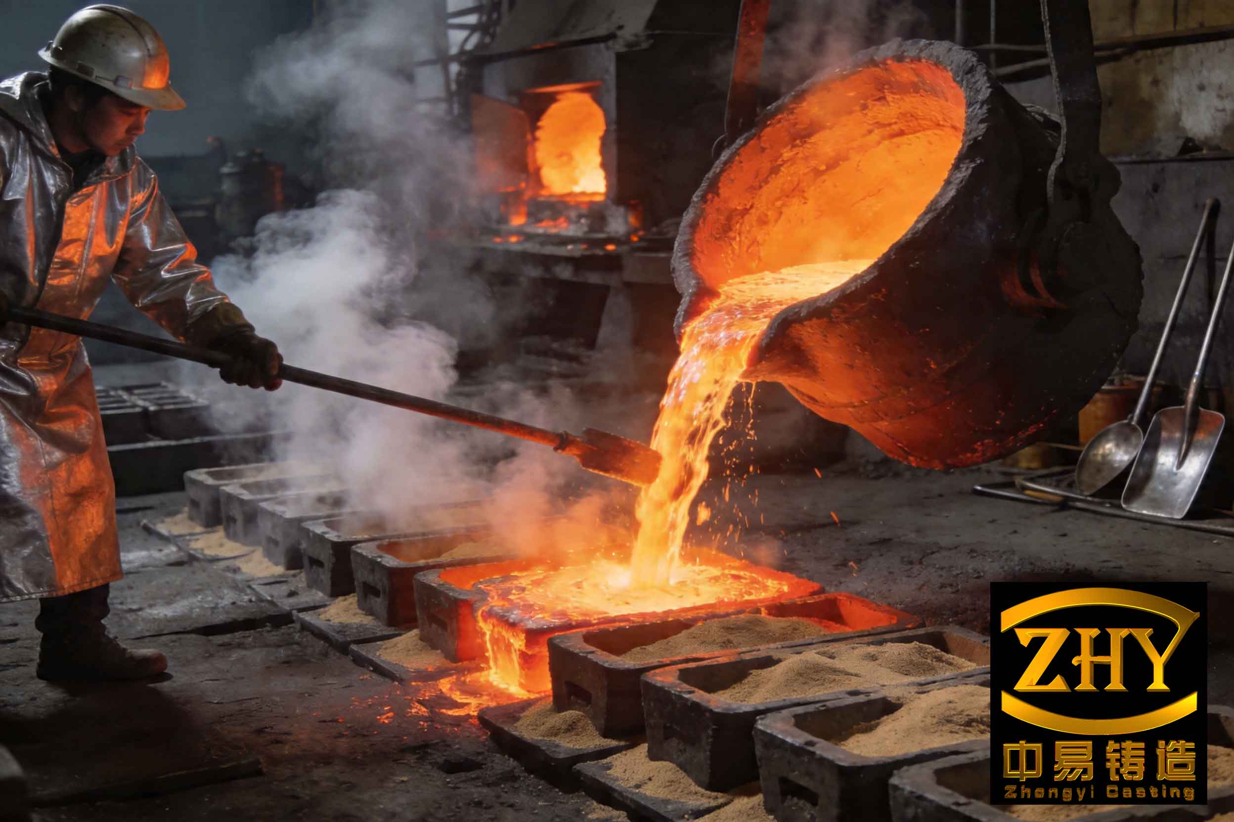
- Pouring Temperature: Maintain as high a pouring temperature as practically possible, consistent with avoiding other defects like shrinkage. A higher temperature (e.g., >1350°C for many castings) lowers metal viscosity, allowing entrapped slag particles more buoyancy to float to the top of the mold cavity before solidification. Many foundries report a drastic reduction in slag inclusion defects when the pouring temperature exceeds a critical threshold.
- Pouring Rate & Technique: Pour steadily and quickly enough to keep the pouring basin full, but avoid excessively high speed that creates turbulence. Use a teapot spout ladle or an automatic pouring system with slag-blocking mechanisms. A teapot ladle draws metal from the bottom, bypassing the slag layer that forms on top.
- Ladle Lining: Use stable, neutral or basic refractory materials for ladle lining. Acidic linings (high in SiO₂) can react with Mg to form low-melting-point silicates that contribute to the slag. The ladle must be properly preheated to avoid thermal shock and metal temperature drop.
3. Molding and Core Materials
The mold environment should be non-oxidizing or reducing to the liquid metal.
4. Gating System Design
A well-designed gating system is a passive but highly effective filter for slag inclusion. Its purpose is to achieve quiescent, non-turbulent filling while actively trapping slag.
| Gating Element | Function & Design Principle |
|---|---|
| Pouring Basin / Cup | Deep enough to maintain a constant metal head; includes a dam or swirl-generator to trap first metal containing slag. |
| Down Sprue | Tapered to prevent aspiration and air entrainment; smooth interior surface. |
| Sprue Well / Slug | A necessary expansion chamber at the base of the sprue to absorb the kinetic energy of the falling stream, preventing turbulence. |
| Runner System | Designed with a primary horizontal runner and secondary vertical gates (e.g., pressurized system). Slag floats and is trapped in the upper part of the horizontal runner. A runner extension beyond the last ingate acts as a slag trap. |
| Ingates | Located at the bottom of the runner to draw metal from below the slag layer. Multiple ingates to distribute flow. |
| Filters (Ceramic or Mesh) | Placed in the runner to physically intercept slag particles. Highly effective but adds cost. |
The critical ratios (e.g., sprue base area : runner area : total ingate area) must be calculated to maintain a pressurized, non-turbulent flow. Vortex formation anywhere in the system is a prime mechanism for slag entrainment.
5. Pouring Practice and Ladle Maintenance
The final execution determines the success of all preceding controls.
Quantitative Relationships and Process Windows
While the above measures are qualitative guidelines, successful control often involves monitoring key relationships. For instance, the risk of slag inclusion can be conceptualized as a function of several variables:
$$ R_{slag} \propto \frac{[S]_0 \cdot [O]_{eff} \cdot \Delta T_{treatment}}{T_{pour} \cdot t_{hold} \cdot [RE]_{res}} $$
Where:
$R_{slag}$ is the relative risk of slag inclusion, $[S]_0$ is the initial sulfur content, $[O]_{eff}$ is the effective oxygen available for reaction, $\Delta T_{treatment}$ is the temperature drop during treatment/holding, $T_{pour}$ is the pouring temperature, $t_{hold}$ is the effective holding/settling time, and $[RE]_{res}$ is the residual rare earth content. This illustrates that minimizing the numerator factors and maximizing the denominator factors reduces the risk.
Furthermore, the temperature at which a stable, troublesome surface oxide film forms is lowered by the presence of surface-active elements like magnesium. The addition of rare earths can modify this film formation temperature $T_{film}$:
$$ T_{film} \approx T_0 – k_{Mg}[Mg] – k_{RE}[RE] $$
Where $T_0$ is the film formation temperature for pure iron, and $k_{Mg}$ and $k_{RE}$ are coefficients. While rare earths may lower $T_{film}$, they make the film more particulate and less continuous, reducing its tendency to be entrained as a thin, damaging slag inclusion film.
In conclusion, combating slag inclusion defects in ductile iron is not about a single silver bullet but requires a holistic, disciplined approach across the entire process. It demands strict control over base iron chemistry, precise and minimal magnesium treatment, effective slag management after treatment, a mold environment that is non-oxidizing, a gating system engineered for slag separation and tranquil flow, and a consistent, high-temperature pouring practice. Each step builds upon the previous one to ensure that the remarkable properties of ductile iron are not compromised by these debilitating internal imperfections. Through diligent application of these interconnected principles, the incidence of slag inclusion can be reduced to minimal levels, ensuring the production of reliable, high-performance ductile iron castings.