
In the production of high-performance diesel engine components, casting defects such as casting holes pose significant challenges to quality control and operational efficiency. Casting holes, often manifested as sand inclusions or voids within the casting structure, can severely compromise the mechanical integrity and durability of critical parts like cylinder heads. This study focuses on a detailed investigation into the occurrence of casting holes in a heavy-duty engine cylinder head, specifically designed for a series meeting stringent emission standards. Through a systematic approach involving fault tree analysis (FTA), experimental validation, and process optimization, we identify root causes and implement effective countermeasures. The objective is to reduce the scrap rate associated with casting holes, thereby enhancing manufacturing yield and product reliability. The findings underscore the importance of meticulous mold design and core quality control in mitigating casting holes, with broader implications for the casting industry.
The cylinder head in question is manufactured using RuT350 ductile iron, a material chosen for its superior strength and thermal properties. The chemical composition is critical to achieving desired material characteristics, as summarized in Table 1. This composition ensures compliance with mechanical performance requirements, including a tensile strength of at least 350 MPa and a hardness range of 170–240 HB. The microstructure specifications demand a vermicular graphite content of no less than 50%, with an optimal range of 80–95%, complemented by spheroidal or aggregate graphite forms. These parameters are essential for withstanding the high stresses and thermal cycles in engine operation. However, the complex geometry of the cylinder head—with a weight of 180 kg, overall dimensions of 1109 mm × 321 mm × 171 mm, and significant wall thickness variations, including minimal sections of 5 mm—exacerbates the susceptibility to casting holes. The horizontal pouring technique employed further amplifies this risk, necessitating a thorough analysis of the defect mechanisms.
| Element | Carbon (C) | Silicon (Si) | Manganese (Mn) | Phosphorus (P) | Sulfur (S) | Chromium (Cr) | Copper (Cu) |
|---|---|---|---|---|---|---|---|
| Range | 3.80–3.95 | 1.95–2.25 | 0.3–0.4 | ≤0.05 | 0.009–0.015 | ≤0.1 | 0.6–0.7 |
Casting holes in this context refer to internal cavities or inclusions caused by foreign sand particles dislodged from the core assembly during the pouring process. These casting holes typically appear as irregular voids within the casting structure, leading to potential leak paths or stress concentration points. The formation of casting holes is often linked to inadequate core design, improper gating system layout, or suboptimal process parameters. To quantify the impact, the initial scrap rate due to casting holes was recorded at 3.95%, contributing significantly to an overall scrap rate of 5.9%. Addressing these casting holes requires a multi-faceted approach, combining analytical tools like FTA with practical modifications in tooling and process control. The following sections delve into the root cause analysis, validation experiments, and implemented solutions, emphasizing the recurrent theme of casting holes throughout the discussion.
The fault tree analysis (FTA) was employed to systematically identify potential sources of casting holes. This method involves constructing a logical diagram that traces the defect back to its fundamental causes, enabling targeted interventions. Based on observations and process audits, several key factors were hypothesized to contribute to the formation of casting holes. These include core structural weaknesses, insufficient core filling during shooting, inappropriate venting arrangements, and design flaws in the gating system. Each of these factors can lead to sand detachment and subsequent entrapment in the molten iron, resulting in casting holes. The FTA results are summarized in Table 2, which categorizes the primary causes and their interrelationships. This analysis highlights that casting holes are not merely random occurrences but are often attributable to specific, addressable issues in the manufacturing chain.
| Primary Cause Category | Specific Factors | Likelihood Contribution to Casting Holes |
|---|---|---|
| Core Design Issues | Inadequate anti-crushing structures, small fitting clearances | High |
| Core Manufacturing Defects | Incomplete sand shooting, localized voids | Medium |
| Mold and Gating Design | Poor venting pin placement, sharp corners in runners | High |
| Process Parameters | Improper pouring temperature or speed | Low |
To validate the hypotheses from the FTA, a series of experiments were conducted. Each potential cause was tested through controlled modifications, with outcomes measured in terms of casting holes incidence. The validation process involved producing limited batches of cylinder heads under adjusted conditions and inspecting for defects. The results, detailed in Table 3, confirm that core design and mold detailing are critical levers for reducing casting holes. For instance, enhancing anti-crushing features on cores led to a complete elimination of casting holes in test samples, underscoring the sensitivity of defect formation to structural integrity. Similarly, optimizing venting and gating geometries showed measurable improvements, reinforcing the notion that casting holes can be mitigated through precise engineering adjustments.
| Potential Cause | Validation Method | Outcome | Impact on Casting Holes |
|---|---|---|---|
| Unreasonable core structure | Added anti-crushing features in core design | Zero casting holes in 10 test units | Significant reduction |
| Small core fitting clearance | Inspected for flash or iron penetration | No flash observed, indicating near-zero clearance | Contributory factor |
| Incomplete core shooting | Used fully filled cores for 30 mold sets | No casting holes detected | Significant reduction |
| Improper sand ring location | Increased distance between sand ring and vent hole by 10 mm | No sand fall-in observed upon inspection | Moderate reduction |
| Poor venting pin placement | Shifted venting pins to avoid direct alignment with vents | No sand ingress into cavity | Moderate reduction |
| Suboptimal gating design | Rounded sharp corners in sprue and runner roots | Scrap rate due to casting holes dropped by 0.5% | Minor but measurable improvement |
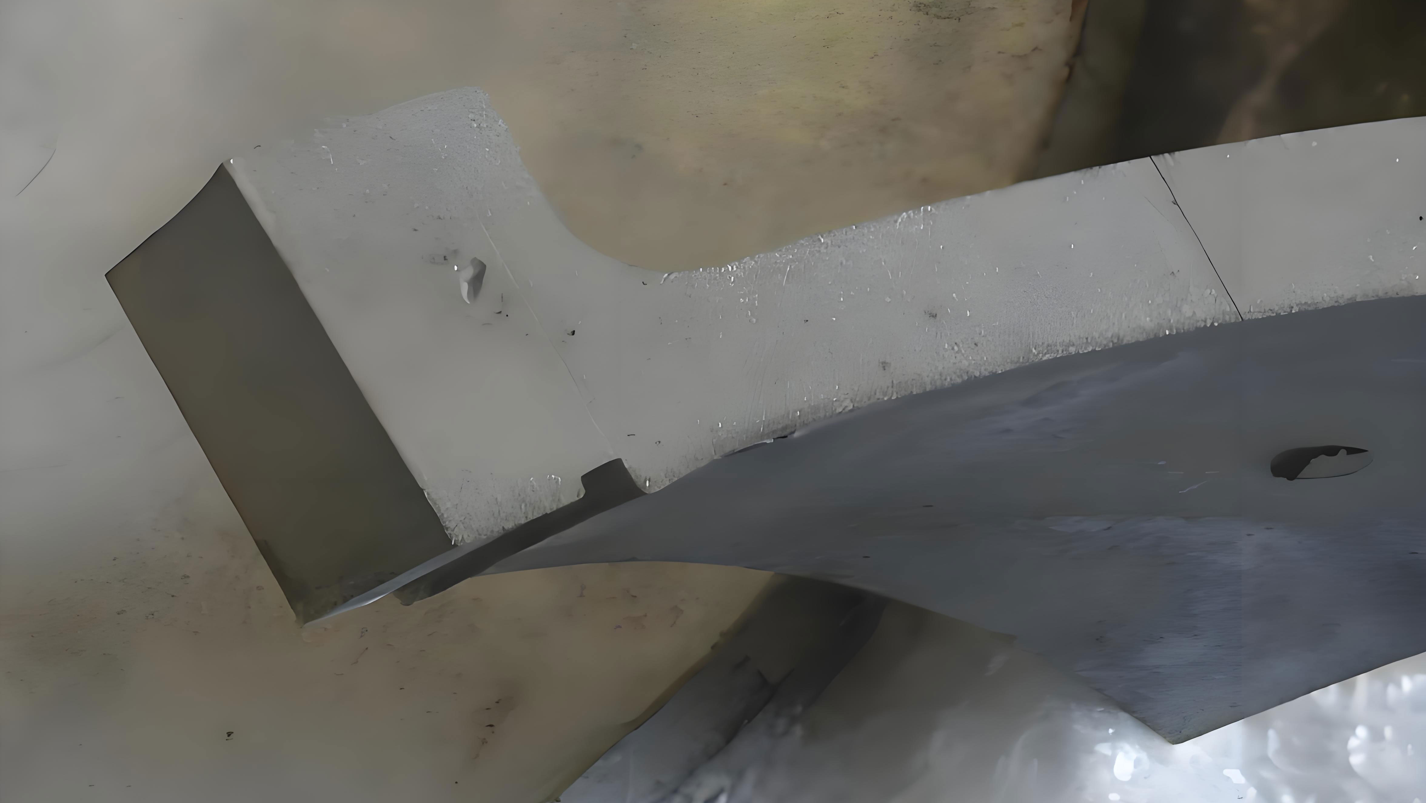
The visual manifestation of casting holes can be observed in typical defect samples, where embedded sand particles create distinct cavities. These casting holes often appear clustered in regions with complex core assemblies or near gating systems. For reference, an image depicting such casting holes is provided below, illustrating the characteristic morphology that necessitates corrective actions. This underscores the importance of visual inspection in diagnosing casting holes and guiding remediation efforts.
Building on the validated causes, a comprehensive set of countermeasures was implemented to address casting holes. These measures focus on modifying mold and core designs, optimizing process parameters, and enhancing quality checks. The first intervention involved increasing the distance between the sand ring and vent holes by 10 mm. This adjustment reduces the likelihood of sand particles being dislodged during core handling or pouring, thereby minimizing the source of casting holes. The modification can be modeled using a probability framework: if the probability of sand detachment is inversely proportional to the distance from vulnerable points, then increasing the distance d reduces the risk R. This relationship can be expressed as: $$ R \propto \frac{1}{d} $$ where a larger d leads to a lower R, directly impacting the incidence of casting holes.
Second, the venting pins were repositioned to avoid direct alignment with vent holes. Misalignment prevents sand from being pushed into the cavity during venting operations, a common precursor to casting holes. The effectiveness of this change can be quantified through fluid dynamics principles. The pressure drop ΔP across a venting system influences sand particle entrainment; by altering pin placement, the pressure distribution is optimized to reduce turbulent flows that dislodge sand. Using Bernoulli’s equation for incompressible flow: $$ P_1 + \frac{1}{2} \rho v_1^2 + \rho g h_1 = P_2 + \frac{1}{2} \rho v_2^2 + \rho g h_2 $$ where P is pressure, ρ is density, v is velocity, g is gravity, and h is height. Adjustments in venting geometry alter v and P, thereby lowering the force available to transport sand particles and form casting holes.
Third, the gating system was redesigned to eliminate sharp corners at the roots of the sprue and runners. Sharp corners create turbulence and stress concentrations, increasing the risk of sand erosion and subsequent casting holes. Rounding these transitions promotes smoother molten metal flow, reducing shear forces on the sand cores. The impact on casting holes can be assessed via the Reynolds number Re, which determines flow regime: $$ Re = \frac{\rho v L}{\mu} $$ where L is characteristic length and μ is dynamic viscosity. Lower turbulence (lower Re) in rounded channels decreases sand particle dislodgement, thus mitigating casting holes. This modification alone contributed to a 0.5% reduction in scrap rate due to casting holes, as noted in validation trials.
Fourth, the core shooting nozzle layout was optimized to ensure uniform sand filling. Incomplete core shooting leaves weak spots prone to collapse under metallostatic pressure, leading to sand ingress and casting holes. By redistributing nozzles, the sand density uniformity improves, enhancing core strength. The strength of a sand core can be approximated by the formula: $$ \sigma_c = k \cdot \rho_s^n $$ where σ_c is compressive strength, ρ_s is sand density, k is a material constant, and n is an exponent. Higher and more uniform ρ_s boosts σ_c, reducing the probability of core failure and associated casting holes. Additionally, anti-crushing rings were incorporated into core designs to provide structural support during assembly and pouring, further safeguarding against sand detachment that causes casting holes.
Fifth, the fitting clearance between core components was increased by 0.5 mm. Initially, near-zero clearances risked core crushing during assembly, generating loose sand particles that result in casting holes. The increased clearance allows for tolerance absorption without compromising seal integrity against molten metal penetration. This adjustment aligns with tolerance stack-up analysis, where the total clearance C_total is summed from individual components: $$ C_{\text{total}} = \sum_{i=1}^{n} C_i $$ By ensuring C_total > 0, assembly stresses are minimized, lowering the generation of sand debris and subsequent casting holes. The combined effect of these measures is summarized in Table 4, which outlines each countermeasure and its theoretical basis for reducing casting holes.
| Countermeasure | Description | Theoretical Basis | Expected Impact on Casting Holes |
|---|---|---|---|
| Increase sand ring-vent distance | Added 10 mm spacing to prevent sand fall-in | Inverse distance-probability model: $$ R \propto 1/d $$ | High reduction |
| Reposition venting pins | Misaligned pins to avoid direct sand push | Bernoulli’s principle for pressure optimization | Moderate reduction |
| Round gating system corners | Eliminated sharp transitions in sprue/runners | Reynolds number reduction for laminar flow: $$ Re = \frac{\rho v L}{\mu} $$ | Moderate reduction |
| Optimize shooting nozzle layout | Redistributed nozzles for uniform sand density | Core strength model: $$ \sigma_c = k \cdot \rho_s^n $$ | High reduction |
| Add anti-crushing rings | Incorporated structural supports in core design | Enhanced mechanical stability under load | High reduction |
| Increase fitting clearance | Expanded clearance by 0.5 mm to prevent crushing | Tolerance stack-up analysis: $$ C_{\text{total}} = \sum C_i $$ | Moderate reduction |
The implementation of these countermeasures led to a significant decline in the occurrence of casting holes. Post-improvement data collected over a production period show a marked reduction in scrap rates. Specifically, the scrap rate attributable to casting holes dropped from 3.95% to 1.97%, representing a 50.2% decrease. Consequently, the overall scrap rate fell from 5.9% to 3.28%, a 44.4% improvement. This outcome validates the effectiveness of the targeted interventions in mitigating casting holes. The trend is illustrated in Figure 5, which compares scrap rates before and after the improvements, highlighting the sustained reduction in casting holes incidence. Such data underscores that casting holes are controllable defects when addressed through systematic design and process refinements.
| Metric | Before Improvement (%) | After Improvement (%) | Reduction (%) |
|---|---|---|---|
| Casting holes scrap rate | 3.95 | 1.97 | 50.2 |
| Overall scrap rate | 5.9 | 3.28 | 44.4 |
The reduction in casting holes can also be analyzed statistically using defect rate modeling. If the initial defect rate for casting holes is p_0, and after improvements it becomes p_1, the relative reduction Δp is given by: $$ \Delta p = \frac{p_0 – p_1}{p_0} \times 100\% $$ Substituting the observed values: $$ \Delta p = \frac{3.95 – 1.97}{3.95} \times 100\% = 50.13\% $$ which aligns closely with the reported 50.2% decrease. This confirms that the countermeasures had a substantial impact on casting holes. Furthermore, the overall quality improvement suggests secondary benefits, such as enhanced mechanical performance and reduced rework costs, all stemming from the focus on eliminating casting holes.
In conclusion, this study demonstrates that casting holes in heavy-duty engine cylinder heads are primarily driven by mold design intricacies and core quality issues. Through a structured approach involving FTA, experimental validation, and targeted modifications, we successfully identified and addressed key factors contributing to casting holes. The implemented countermeasures—including increased sand ring-vent distances, venting pin realignment, gating system rounding, nozzle layout optimization, anti-crushing ring addition, and fitting clearance adjustments—collectively reduced the scrap rate due to casting holes by over 50%. These findings emphasize that meticulous attention to design details and process control is paramount in mitigating casting holes. The insights gained are applicable to similar casting operations, where casting holes remain a prevalent challenge. Future work could explore advanced simulation tools to predict casting holes formation and further optimize parameters, continuing the pursuit of zero-defect manufacturing in foundry environments.