
In the context of the rapid advancement of the automotive engine industry and the stringent demands for vehicle lightweighting, the extensive application of aluminum alloys has become a dominant trend. Castings are evolving towards being lighter, more precise, stronger, and more composite. Among engine components, aluminum alloy cylinder blocks and heads have seen a significant increase in their proportion. However, due to their complex structure, intricate manufacturing processes, and high quality requirements, aluminum cylinder heads often suffer from a high scrap rate, which directly impacts product quality and cost. The internal cavities of an engine cylinder head, including water jackets, oil galleries, and intake/exhaust ports, are particularly complex with varying wall thicknesses. This non-uniformity predisposes these areas to casting defects such as shrinkage porosity and shrinkage cavities, commonly referred to collectively as shrinkage in casting. These defects can severely compromise the performance and pressure tightness of the final component.
This article, based on practical experience, analyzes a persistent issue of leakage in the water and main oil galleries of a specific series of cylinder heads caused by shrinkage in casting defects. It explores the root causes and details a series of successful optimization measures implemented through modifications to both the product design and the die-casting模具, ultimately enhancing casting quality and yield.
1. Understanding Shrinkage Defects: Mechanisms and Contributing Factors
Shrinkage in casting refers to the formation of voids or porous regions within a solidified casting. These defects arise during the solidification phase when the volumetric contraction of the liquid metal, as it transitions to solid, is not adequately compensated by the influx of additional molten metal from the feeding system. The formation can be systematically understood through the following sequence and governing physical principles.
The total volumetric contraction, $V_{total}$, from pouring temperature to room temperature can be expressed as the sum of three components:
$$V_{total} = V_{liquid} + V_{liquid-solid} + V_{solid}$$
Where:
- $V_{liquid}$ is the contraction of the liquid metal from pouring temperature to the liquidus temperature.
- $V_{liquid-solid}$ is the contraction during the liquid-solid phase change (solidification shrinkage), which is the most critical for defect formation.
- $V_{solid}$ is the contraction of the solid metal from the solidus temperature to room temperature.
For most aluminum alloys, the solidification shrinkage, $V_{liquid-solid}$, is approximately 6-7% by volume. If this contraction is not fed, it manifests as shrinkage in casting. The propensity for defect formation is governed by local thermal conditions and feeding paths. A simplified criterion for soundness is the Niyama criterion, often used in simulation, which relates the temperature gradient $G$ and the cooling rate $\dot{T}$:
$$Niyama = \frac{G}{\sqrt{\dot{T}}}$$
Regions with a low Niyama value are prone to shrinkage in casting (microporosity).
The primary factors influencing the severity and location of shrinkage in casting are summarized in the table below:
| Factor Category | Specific Influence | Effect on Shrinkage |
|---|---|---|
| Thermal Parameters | Excessively high pouring temperature; Improper mold temperature gradient. | Promotes a long, wide mushy zone, hindering directional solidification and interdendritic feeding, leading to dispersed shrinkage in casting. |
| Geometric Design | Abrupt changes in section thickness; Presence of isolated heavy sections (hot spots). | Thick sections solidify last, creating thermal centers. If these hot spots lack effective feeding channels, macroscopic shrinkage cavities form. |
| Feeding System Design | Inadequate ingate size or premature freezing of feeding paths; Insufficient applied pressure. | Prevents the transfer of metallostatic or applied pressure to the solidifying region, terminating feeding prematurely and causing shrinkage in casting. |
| Filling Dynamics | Turbulent metal flow during mold filling. | Can entrap air or gas, creating isolated pockets. Subsequent solidification shrinkage in these pockets leads to shrinkage porosity, often combined with gas pores. |
2. Case Study: Leakage in a Specific Cylinder Head Series
The subject of this analysis is a cylinder head series produced for high-performance passenger vehicle engines. The casting process employed is low-pressure die casting (LPDC) into permanent metal molds. Core sands form the complex internal passages. Key process parameters were: pouring temperature range of 695–720°C and mold temperature controlled between 250–300°C.
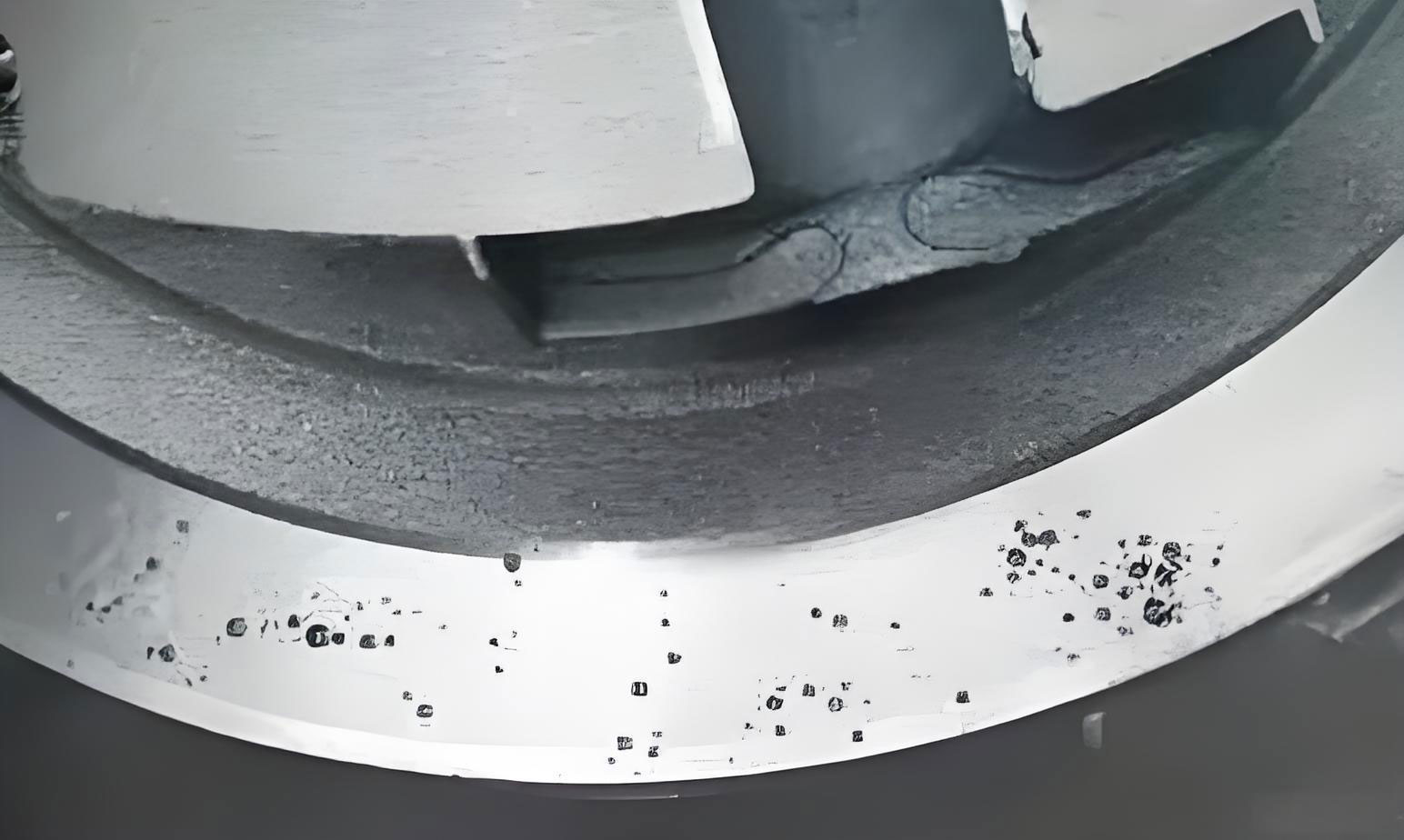
Despite meeting stringent requirements for dimensional accuracy and surface finish, a critical quality issue emerged post-machining: pressure leakage tests revealed failures in the water jacket and, predominantly, the main oil gallery. The scrap rate attributable to this leakage reached an unacceptable 20%. Metallurgical dissection of failed castings revealed extensive shrinkage in casting defects in the walls surrounding these passages.
2.1 Root Cause Analysis
A systematic investigation, combining physical dissection, process review, and Computer-Aided Engineering (CAE) simulation, pinpointed three interrelated root causes for the severe shrinkage in casting.
2.1.1 Isolated Heavy Section with No Feeding Path
The main oil gallery is located at the uppermost deck face of the cylinder head. This area inherently formed the thickest section of the entire casting, acting as a massive thermal “hot spot.” Crucially, this heavy section was surrounded by thinner walls and core prints, with no designed channel to allow molten metal from the feeding system to reach and compensate for its solidification shrinkage. According to Chvorinov’s rule, solidification time $t_s$ is proportional to the square of the volume-to-surface-area ratio:
$$t_s = k \left( \frac{V}{A} \right)^2$$
Where $k$ is the mold constant. The high $(V/A)^2$ ratio for the oil gallery area meant it solidified last, starving for liquid feed and resulting in a concentrated shrinkage cavity.
2.1.2 Detrimental Effect of a Poorly Designed Cast-in Chill
In an initial attempt to mitigate the thick section, a small, protruding cast-in steel chill (pre-cast core) was incorporated into the permanent mold at the oil gallery location. The intent was to reduce the effective local wall thickness and extract heat. However, due to its small size and mass, this chill lacked sufficient cooling capacity. During the rapid cycling of the LPDC process, the chill itself became overheated, effectively acting as an insulator rather than a heat sink. This exacerbated the local thermal accumulation, worsening the condition for shrinkage in casting formation around it.
2.1.3 Turbulent Filling Leading to Shrinkage Porosity in the Water Jacket
CAE flow simulation of the original gating and cavity design revealed a significant flow disturbance during filling. The metal stream exhibited a “back-filling” or recirculation pattern in certain regions adjacent to the water jacket core. This turbulence entrapped air bubbles. Upon solidification, the shrinkage of the metal surrounding these isolated gas pockets, combined with the gas pressure itself, resulted in a spongy, interconnected network of shrinkage porosity (shrinkage in casting of the microporosity type). This porous structure provided a path for fluid leakage during pressure testing.
3. Implemented Solutions and Technical Rationale
To address the root causes, a multi-faceted improvement plan was devised and executed, focusing on geometry modification, thermal management, and flow optimization.
3.1 Creating an Effective Feeding Channel
The most critical intervention was the introduction of a dedicated feeding channel to the main oil gallery hot spot. The solution involved modifying the sand core tooling for the oil gallery. A semi-cylindrical protrusion was added to the core box, which created a corresponding hole or channel in the finished sand core. During casting, this channel connects the problematic thick section directly to a lower, earlier-solidifying part of the casting that is well-fed by the gating system.
This design establishes a controlled “feed path.” The pressure from the low-pressure system can now act through this channel, pushing liquid metal to compensate for the solidification shrinkage occurring in the oil gallery wall until the channel itself freezes. The effectiveness relies on ensuring the channel solidifies after the hot spot it feeds, a principle governed by the solidification time calculation mentioned earlier. The modification is conceptually a change from an “isolated” to a “fed” thermal node, dramatically reducing the risk of gross shrinkage in casting.
3.2 Removal of the Counterproductive Cast-in Chill
The small, overheated cast-in steel chill was completely removed from the permanent mold. This eliminated the unintended insulating effect, allowing the mold wall itself to extract heat more uniformly from the area. While this slightly increased the nominal local wall thickness, it created a more predictable and manageable thermal profile. The benefit of removing a negative factor outweighed the minor increase in section size, especially when coupled with the new feeding channel.
3.3 Optimization of Filling to Eliminate Turbulence
Based on the CAE analysis, specific areas of the mold cavity and core geometry that were causing abrupt flow direction changes or impingement were identified and redesigned. The modifications included smoothing transitions, adding slight radii to sharp corners, and subtly altering the alignment of certain features. The goal was to promote a more laminar, progressive front-wise filling pattern, minimizing air entrapment. This reduced the formation of isolated gas pockets that would later evolve into leakage-prone zones of combined gas and shrinkage in casting porosity in the water jacket region.
| Improvement Measure | Targeted Root Cause | Primary Mechanism | Expected Impact on Shrinkage |
|---|---|---|---|
| Add Feeding Channel in Oil Core | Isolated heavy section (Hot spot) | Provides direct liquid metal feed path for solidification shrinkage compensation. | Eliminates major shrinkage cavity. |
| Remove Small Cast-in Chill | Overheated local insulation | Restores uniform mold cooling; removes parasitic heat source. | Reduces thermal gradient anomaly promoting shrinkage. |
| Optimize Cavity/Core Geometry | Turbulent filling & air entrapment | Promotes laminar fill, reducing gas entrapment that evolves into shrinkage porosity. | Reduces dispersed micro-shrinkage/porosity. |
4. Results and Quantitative Impact Assessment
The implementation of these combined measures yielded a dramatic improvement in casting quality. Post-modification dissection of sample castings confirmed the complete elimination of the large, concentrated shrinkage cavity in the main oil gallery wall. The microstructure in previously problematic areas showed significantly denser, sounder material.
The most critical Key Performance Indicator (KPI), the leakage failure rate after machining and pressure testing, showed remarkable improvement. The failure rate dropped from the initial 20% to a sustained level of approximately 5%. This represents a 75% reduction in scrap attributed to this specific defect.
The financial impact is substantial. Considering an estimated fully-loaded cost per casting (including materials, energy, machining up to the leak test) and an annual production volume for this series, the cost avoidance can be calculated. The formula for annual scrap cost savings ($S$) is:
$$S = N \times C \times (R_i – R_f)$$
Where:
- $N$ = Annual production volume (e.g., 25,000 pieces)
- $C$ = Cost per casting at the leak test stage (e.g., 300 monetary units)
- $R_i$ = Initial scrap rate (0.20)
- $R_f$ = Final scrap rate (0.05)
Plugging in the numbers:
$$S = 25,000 \times 300 \times (0.20 – 0.05) = 25,000 \times 300 \times 0.15 = 1,125,000$$
This results in annual cost savings of approximately 1.125 million monetary units, a clear demonstration of the value of targeted technical problem-solving for shrinkage in casting.
| Performance Indicator | Before Improvements | After Improvements | Improvement |
|---|---|---|---|
| Leakage Scrap Rate (Water/Main Oil Gallery) | 20% | 5% | -75% (15 percentage points) |
| Presence of Gross Shrinkage Cavity (Oil Gallery) | Severe, consistent | Eliminated | 100% removal |
| Estimated Annual Scrap Cost (for this defect) | High (Base + 15% variable) | Reduced to base level | ~1.125M unit savings |
5. Conclusions and Generalized Learnings
The successful resolution of this leakage issue provides several broadly applicable lessons for preventing shrinkage in casting in complex structural components like cylinder heads:
1. Proactive Design for Manufacturability (DFM): The most robust solution for heavy sections prone to shrinkage in casting is to address them during the initial product design phase. Engineers should collaborate with foundry experts to either avoid isolated thermal masses or integrate natural feeding paths (like ribs or channels) into the component geometry. Retrofitting such features later is always more challenging and costly.
2. Strategic Use of Chills and Feeders: Chills (whether cast-in or external) are powerful tools but must be designed correctly. A chill must have sufficient thermal mass and cooling capacity to effectively extract heat. A poorly sized chill can become a liability. Similarly, the design of feeding channels (risers, feed paths) must follow solidification principles, ensuring they remain liquid longer than the section they are intended to feed.
3. The Primacy of Feeding for Gross Shrinkage: For major shrinkage cavities in heavy sections, establishing a functional feeding path is often the only definitive solution. However, the location of such feed paths must be carefully planned in conjunction with machining operations. A feeding channel that is intersected by a subsequent machining operation (like a drill) can cause tool breakage or leave an undesirable surface defect, simply trading one problem for another.
4. Holistic Process Analysis: Solving complex casting defects like leakage rarely has a single root cause. A holistic approach combining physical analysis (like sectioning), process parameter review, and advanced simulation (CAE for fluid flow and solidification) is essential. This case showed that both gross shrinkage from poor feeding and micro-shrinkage from turbulent filling needed to be addressed simultaneously for complete success.
In summary, the battle against shrinkage in casting is a fundamental aspect of foundry engineering. It requires a deep understanding of solidification science, thoughtful product and tooling design, and a systematic, data-driven approach to problem-solving. The experience detailed here underscores that significant quality and cost improvements are achievable through targeted technical interventions grounded in these principles.