
In the field of heavy-duty locomotive manufacturing, the integrity of critical components is paramount for operational safety and reliability. As a researcher engaged in casting process development, I encountered significant challenges during the trial production of a large-scale yoke steel casting, where severe casting defects emerged. These casting defects, primarily manifested as cracks and gas pores, threatened the component’s performance and necessitated a thorough investigation. This article details my first-hand analysis of these casting defects, the root causes identified through metallurgical and process examinations, and the systematic improvements implemented to eradicate them. The yoke, a key rotational part in high-power diesel locomotives, is manufactured from ZG230-450 cast steel and requires full machining and stringent non-destructive testing. The initial casting process failed to meet these demands, revealing the critical need for a deeper understanding of defect formation mechanisms in thick-section steel castings.
The yoke casting possesses a typical rotational symmetry design. Its primary geometry consists of a bottom flange and a top section featuring five circumferentially arranged plum-blossom shaped lightening holes. The overall external dimensions are approximately 710 mm in diameter and 760 mm in height. The wall thickness varies significantly: the flange and side walls have an average thickness of 78 mm, while the top section surrounding the lightening holes averages 140 mm. The entire surface is machined, and the final component weighs about 800 kg. The material specification, ZG230-450, indicates a carbon steel with moderate strength and considerable solidification shrinkage, which inherently increases its susceptibility to shrinkage porosity and thermal stresses, key precursors to casting defects.
The initial casting process was designed around a vertical pouring orientation to promote directional solidification. The molding utilized a three-box system with self-curing furan resin sand. The gating system was a stepped design, and the top surface (plum-blossom hole face) was oriented upwards and fitted with insulating risers to feed the thick section. The plum-blossom holes themselves were not cored but were intended to be machined out subsequently to avoid potential core burning and sand fusion issues in the riser’s hot spot. To control the solidification rate of the bottom flange, five shaped chills were placed at equal intervals around its circumference. The pouring temperature was set at 1580°C, with a pouring time of 30 seconds. This setup, while theoretically sound, led directly to the manifestation of critical casting defects.
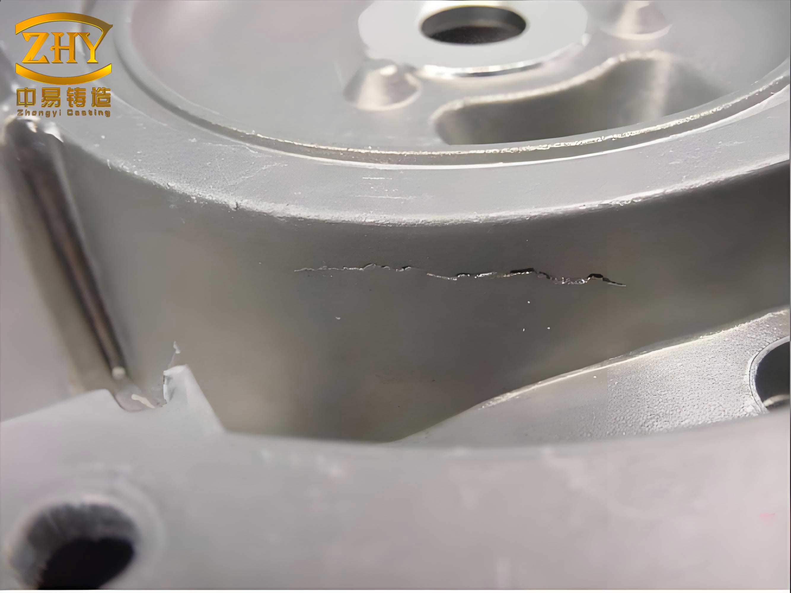
Upon shakeout and initial inspection, the castings exhibited two dominant types of casting defects. The first and most alarming was a series of cracks on the bottom flange. Five distinct radial cracks were visible to the naked eye, originating from the inner edge of the flange and propagating outwards. These cracks were nearly linear, with surfaces appearing dark and oxidized. Their depth reached up to 15 mm, with widths around 1 mm, indicating they were hot tears formed during the late stages of solidification. The second type of casting defect emerged during machining: numerous scattered gas pores and slag inclusions were found on the top surface around the machined lightening holes. These pores were rounded or elliptical, with smooth edges and contained dark oxides, confirming them as gas-entrapment and slag-related casting defects.
The investigation into these casting defects was multi-faceted, focusing on chill design, mold properties, and melting/pouring parameters. A summary of the key factors analyzed is presented in the table below.
| Factor Category | Initial Condition | Suspected Influence on Casting Defects |
|---|---|---|
| Chill Design | 5 chills, 50mm thick, equally spaced. | Creates severe thermal gradients, leading to tensile stress and hot tearing in inter-chill zones. |
| Mold/Core Yield | Solid furan sand core. | Poor yield resistance, hindering contraction and promoting high residual stress. |
| Pouring Temperature | 1580°C | Exacerbates coarse grain structure, widens mushy zone, and increases thermal stress. |
| Riser Coverage | Single large riser on top. | Inadequate for feeding and venting the entire top surface, trapping gas and slag. |
| Chemical Composition | Within ZG230-450 spec (see Table 2). | Presence of P, S lowers eutectic temperature, widening solidification range. |
The chemical composition of the failed casting was verified and found to be within specification, as shown in Table 2. While elements like phosphorus and sulfur are known to promote hot tearing by forming low-melting-point eutectics and widening the solidification range, their levels here were not excessively high. Thus, they were a contributing factor but not the primary cause of the observed casting defects.
| C | Si | Mn | P | S |
|---|---|---|---|---|
| 0.22 | 0.56 | 0.59 | 0.018 | 0.021 |
The fundamental mechanics behind the crack formation, a critical category of casting defects, can be modeled. Hot tearing susceptibility is often linked to the strain accumulation in the mushy zone during the final stages of solidification. The strain rate ($\dot{\varepsilon}$) must be accommodated by liquid feeding or result in tear formation. A simplified model considers the thermal stress ($\sigma_{th}$) generated due to constrained cooling:
$$ \sigma_{th} = E \cdot \alpha \cdot \Delta T $$
where $E$ is the Young’s modulus at elevated temperature, $\alpha$ is the coefficient of thermal expansion, and $\Delta T$ is the temperature difference across a region or between different regions of the casting. In the flange, the regions in contact with the chills (Zone A) cool and solidify rapidly, while the regions between chills (Zone B) cool slowly through the sand mold. This creates a significant $\Delta T$ between these zones. As Zone A solidifies and contracts, it exerts a compressive stress on the still-mushy Zone B. Later, when Zone B solidifies and contracts, it is constrained by the already solid Zone A, leading to tensile stress ($\sigma_{tensile}$) in Zone B. Cracking occurs when:
$$ \sigma_{tensile} \geq \sigma_{fracture}(T) $$
where $\sigma_{fracture}(T)$ is the fracture strength of the material at the coherent solid network temperature within the mushy zone. The initial chill arrangement maximized this detrimental $\Delta T$. Furthermore, the poor yielding of the solid sand core provided additional constraint, effectively increasing the apparent $E$ in the stress equation and raising $\sigma_{tensile}$. The high pouring temperature of 1580°C increased the total contraction and the width of the mushy zone (fraction solid $g_s$ between 0.4 and 0.9), making the material vulnerable for a longer period. The susceptibility can be related to the solidification time ($t_f$) and temperature gradient ($G$). A longer local solidification time in Zone B, combined with a high thermal gradient from Zone A to B, creates ideal conditions for these casting defects.
The gas and slag defects on the top surface were analyzed differently. During solidification, gases like hydrogen and nitrogen, as well as non-metallic inclusions, are rejected from the solidifying metal and float upwards. In the initial design, the single large riser covered only the central portion of the top conical surface. The gases and slags migrating to the peripheral areas, especially near the edges of the lightening holes, became trapped. The relatively poor permeability of the dense furan sand mold above these areas hindered venting. The defect formation can be conceptualized by considering the buoyant velocity ($v_b$) of a gas bubble or inclusion:
$$ v_b = \frac{2 (\rho_m – \rho_i) g r^2}{9 \eta} $$
where $\rho_m$ is the molten metal density, $\rho_i$ is the inclusion/gas bubble density, $g$ is gravity, $r$ is the particle radius, and $\eta$ is the metal viscosity. While these entities rise, the advancing solidification front from the sides and bottom can encapsulate them if the feeding path is blocked or if they accumulate in a dead zone. The top surface, being the last to solidify, should act as a sink for these casting defects. However, the limited riser area and the conical geometry created regions where the solidification front advanced from the edges, pocketing the buoyant material before it could reach the riser. The presence of dark oxides within the pores confirmed that slag inclusions were also trapped, indicating a combined defect origin.
To eliminate these persistent casting defects, a targeted and integrated set of process modifications was devised and implemented. The improvements directly addressed each root cause identified in the analysis.
1. Crack Mitigation Strategies:
Chill Layout Optimization: The number of flange chills was reduced from five to four, increasing the angular spacing between them. The chill thickness was maintained at 50 mm. Crucially, the sand in the gap between adjacent chills was replaced with chromite sand of equivalent thickness. Chromite sand has a higher chilling power and thermal conductivity than silica sand, though less than steel chills. This modification served to reduce the drastic thermal gradient between the chill zone and the inter-chill zone, promoting more uniform cooling and lowering the tensile stress ($\sigma_{tensile}$) in the inter-chill areas. The new layout complied with established foundry principles where chill spacing should be about 1/2 to 2/3 of the chill length.
Enhancing Mold Yield: The large central core was redesigned to be hollow, incorporating an internal reinforcing骨架 (core frame) to maintain strength while drastically improving its collapsibility. This reduced the constraint on the contracting casting, effectively lowering the Young’s modulus term ($E$) in the thermal stress equation during the critical cooling phase, thereby minimizing the driving force for crack initiation.
Pouring Temperature Adjustment: The pouring temperature was carefully lowered to a range of 1550°C – 1570°C. This reduction decreased the total volume of superheat, minimized the mushy zone width, promoted finer grain structure, and reduced the overall thermal gradients ($\Delta T$) within the casting. The goal was to find the optimal temperature that ensured complete filling without exacerbating the conditions that lead to casting defects like hot tears.
2. Gas and Slag Defect Elimination Strategy:
Riser System Enhancement: To address the venting and feeding insufficiency on the top surface, two additional side-risers were introduced symmetrically on the top plane, flanking the original central riser. This provided significantly greater coverage of the top surface area. These risers, also made insulating, created multiple high-temperature, last-to-solidify zones. This design effectively provided extended escape routes for buoyant gases and inclusions. The metal in these riser necks remained liquid longer, allowing more time for $v_b$ to carry defects into the riser volumes rather than being trapped in the casting body. The system now functioned as an effective slag and gas trap, purifying the metal in the critical top section.
The synergistic effect of these changes is summarized in the table below, contrasting the key parameters before and after the process optimization aimed at mitigating casting defects.
| Process Parameter | Initial Process | Optimized Process | Impact on Casting Defects |
|---|---|---|---|
| Number of Chills | 5 | 4 | Reduced thermal stress concentration. |
| Inter-Chill Material | Silica Sand | Chromite Sand | More uniform cooling, lower ΔT. |
| Core Structure | Solid | Hollow with frame | Improved yield, lower constraint stress. |
| Pouring Temperature | 1580°C | 1550-1570°C | Reduced mushy zone, finer grains, lower stress. |
| Top Riser Configuration | One central riser | One central + two side risers | Enhanced feeding, venting, and slag trapping. |
The modified process was put into production. After a controlled cooling period of 48 hours, the castings were shaken out. Visual inspection revealed no traces of cracks on the flange surfaces. Non-destructive testing was conducted rigorously. Wet magnetic particle inspection over the entire casting surface showed no linear indications, meeting the stringent requirements of relevant standards (equivalent to ASTM E186 Class 2). Subsequent machining of the plum-blossom holes and other surfaces proceeded smoothly without revealing any sub-surface gas pores or slag inclusions. Finally, full-section radiographic examination confirmed the internal soundness of the castings, with no detectable shrinkage cavities, porosity, or cracks. The optimized process had successfully eliminated both major categories of casting defects.
This case study underscores the complexity involved in producing sound thick-section steel castings. The initial presence of severe casting defects served as a catalyst for a detailed forensic investigation. The analysis revealed that the cracks were not due to a single factor but a confluence of unfavorable conditions: an aggressive chill layout inducing high thermal stress, a rigid mold system providing excessive constraint, and a high pouring temperature that extended the vulnerability window. The surface gas pores were a direct result of inadequate venting and slag collection capacity in the original riser design. The implemented solutions were holistic. The chill modification balanced cooling rates, the hollow core improved system yield, the lowered pouring temperature refined the solidification structure, and the expanded riser system provided an effective purification mechanism. Each change contributed to altering the fundamental parameters in the stress and defect formation equations. The complete elimination of these casting defects validates the analytical approach and demonstrates that a scientific understanding of solidification mechanics, thermal stress development, and fluid dynamics within the mold is essential for robust casting process design. This experience provides a valuable framework for addressing similar casting defects in other heavy steel castings, emphasizing that prevention is always more efficient than correction in the realm of metal casting.