
In my extensive experience within the foundry industry, addressing internal defects in heavy-section castings remains a paramount challenge. Among these, shrinkage in casting is a particularly persistent issue that can severely compromise the structural integrity and service life of critical components. This article delves into a detailed, first-person investigation and optimization journey focused on eliminating shrinkage porosity in large ductile iron wind turbine hubs. As a key component, the wind turbine hub must exhibit exceptional longevity, high strength, vibration damping, and reliability. It bears and transmits loads from the blades while also facilitating pitch control for optimal energy capture. The manufacturing process imposes stringent technical requirements, including specific metallographic structures, low-temperature impact tests, ultrasonic examination, and magnetic particle inspection. My work centers on the analysis and rectification of shrinkage in casting defects in these hubs, employing computational simulation and iterative process design to achieve robust, defect-free production.
The initial casting process for a QT400-18AL ductile iron hub was plagued by subsurface shrinkage defects discovered during machining. The hub’s substantial dimensions—approximately 3670 mm in diameter and 3830 mm in height, with a casting weight of 23.7 tons—and varying wall thicknesses (from 52 mm to a maximum of 230 mm) created inherent solidification challenges. The original process utilized a single-casting-per-mold approach with a vertical orientation. The gating system was a bottom-feeding, dispersed design with one 100 mm diameter sprue, three 80 mm diameter runners, and eighteen 60 mm diameter ingates. Six Ø280 mm insulating risers were placed on the main shaft face, interspersed with several chills (200 mm x 100 mm x 70 mm). The chemical composition was controlled within: C: 3.90-3.95%, Si: 1.95-2.05%, with a pouring temperature of 1360-1370°C. Despite these measures, ultrasonic testing (UT) and machining revealed unacceptable shrinkage in casting zones, particularly around bolt holes on the main shaft face.
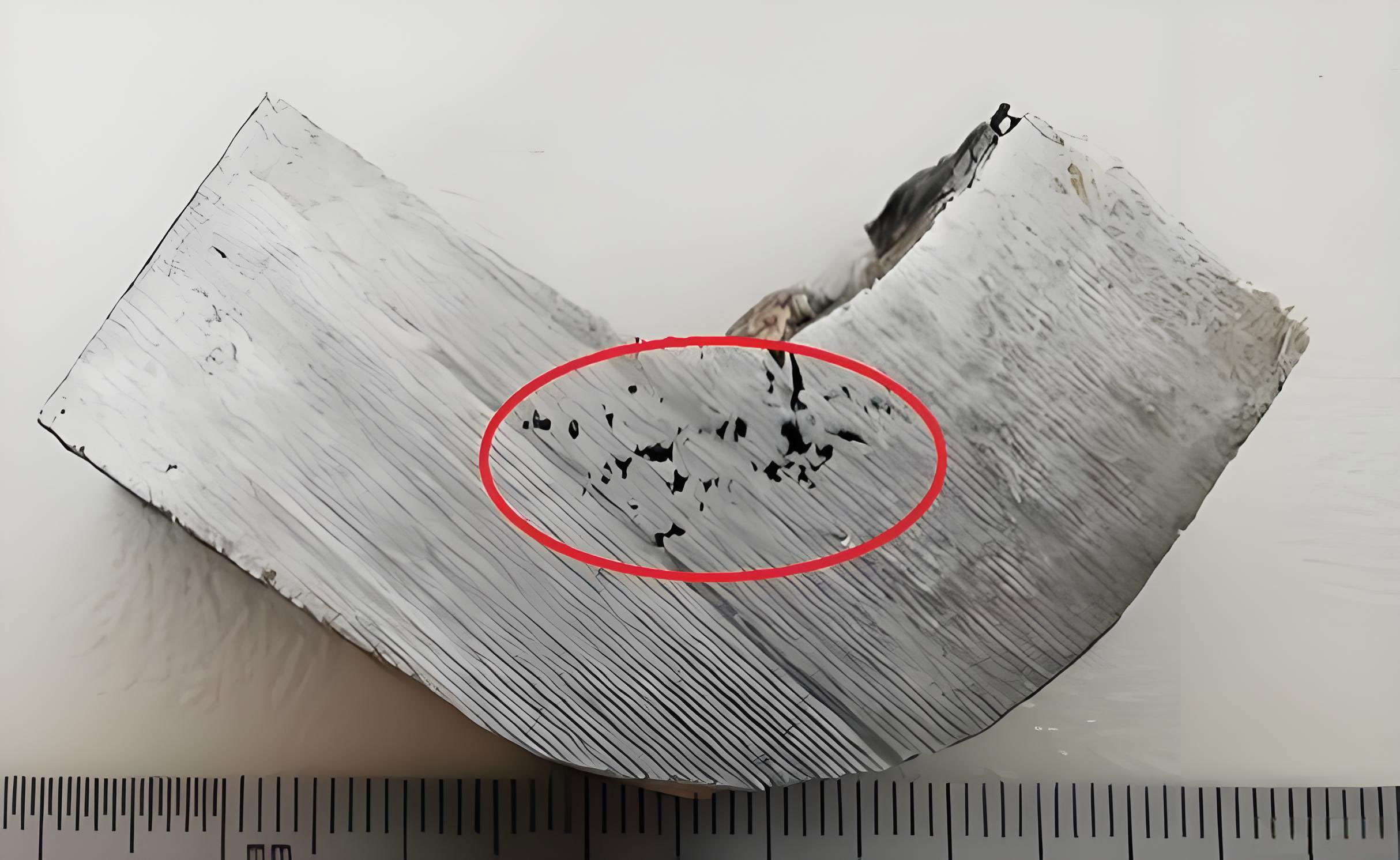
My first step was to conduct a thorough defect analysis. Macroscopic examination and microscopy of the affected areas revealed rough, irregular cavities with dendritic structures and oxide inclusions, unequivocally identifying them as shrinkage porosity. To understand the root cause, I employed MAGMA solidification simulation software. The simulation predicted a high probability of porosity, or shrinkage in casting, precisely in the problematic regions: the main shaft face and its junction with the hub’s web. The fundamental issue lies in the solidification characteristics of ductile iron. Its wide freezing range and significant graphitization expansion can lead to dispersed micro-shrinkage if the thermal gradients and feeding paths are not optimally controlled. The inherent volume deficit arises from the sum of liquid and solidification shrinkage exceeding the subsequent solid-state contraction. This phenomenon is mathematically described by considering the mass conservation during phase change. The fundamental condition for shrinkage in casting formation can be expressed as a deficit in fed volume:
$$ V_{\text{shrinkage}} = \int_{t_{\text{liquidus}}}^{t_{\text{solidus}}} \left( \beta_l(T) + \beta_s(T) – \alpha_s(T) \right) \cdot \frac{dV}{dt} \, dt $$
Where:
- $V_{\text{shrinkage}}$ is the volume of shrinkage porosity formed.
- $\beta_l(T)$ is the temperature-dependent coefficient of liquid contraction.
- $\beta_s(T)$ is the temperature-dependent coefficient of solidification contraction.
- $\alpha_s(T)$ is the temperature-dependent coefficient of solid-state contraction.
- $dV/dt$ represents the volumetric solidification rate.
For ductile iron, the graphitization expansion ($\gamma_g$) provides a counteracting force, making the net shrinkage behavior highly sensitive to cooling rates and mold rigidity. The modified criterion becomes:
$$ V_{\text{net}} = \int \left( \beta_l + \beta_s – \alpha_s – \eta \cdot \gamma_g \right) \, dV $$
Here, $\eta$ is an efficiency factor for utilizing the graphite expansion for self-feeding. In the hub’s thick sections, slow cooling reduces thermal gradients, prolonging the mushy zone and trapping liquid pockets, leading to the observed dispersed shrinkage in casting. The table below summarizes the key parameters influencing shrinkage formation in this context:
| Parameter | Symbol | Typical Range for Ductile Iron | Effect on Shrinkage Tendency |
|---|---|---|---|
| Casting Modulus | $M_c = V/A$ | > 4 cm (for thick sections) | Higher modulus increases thermal mass and shrinkage risk. |
| Carbon Equivalent | $CE = \%C + 0.33(\%Si)$ | ~4.3 – 4.5 | High CE increases graphitization expansion, can reduce shrinkage if controlled. |
| Cooling Rate | $dT/dt$ | Variable (0.1 – 10 °C/s) | Slow rate promotes dispersed shrinkage; fast rate promotes directional solidification. |
| Feeding Distance | $L_f$ | ~4-6 times wall thickness | Exceeding this limit leads to underfed regions and shrinkage. |
| Riser Modulus | $M_r$ | Should be $M_r > 1.2 M_c$ | Insufficient riser modulus causes inadequate liquid feed. |
In the initial process, calculation showed the hub’s main shaft section had a modulus ($M_c$) of approximately 5.96 cm, while the insulating risers had a modulus ($M_r$) of only about 5.91 cm. Since $M_r < M_c$, the risers solidified before the casting section, ceasing liquid feed prematurely and creating ideal conditions for shrinkage in casting to form. This analytical insight guided my subsequent process optimization efforts, which proceeded through three distinct, iterative schemes.
Process Optimization Schemes: A Systematic Approach to Eliminate Shrinkage in Casting
My strategy was to transform dispersed shrinkage into concentrated porosity that could be reliably redirected into the risers, while simultaneously enhancing the utilization of graphitization expansion for self-feeding. This involved manipulating the thermal field through riser design and strategic chilling.
Scheme A: Enhanced Riser Capacity
The first logical step was to increase the feeding capacity. I replaced the six Ø280 mm insulating risers with larger Ø350 mm risers. The goal was to ensure $M_r > 1.2 M_c$, providing a longer-lasting liquid reservoir. The governing equation for riser sizing based on Chvorinov’s rule is:
$$ t_{\text{solidification}} = k \cdot \left( \frac{V}{A} \right)^2 = k \cdot M^2 $$
Where $k$ is the mold constant. For a riser to feed effectively, its solidification time ($t_r$) must exceed that of the casting section ($t_c$):
$$ t_r > t_c \implies M_r > M_c $$
With the larger risers, $M_r$ was recalculated to be ~6.85 cm, theoretically satisfying the criterion. However, post-casting UT inspection revealed that shrinkage in casting defects persisted in similar locations. The failure indicated that merely increasing riser size was insufficient. The underlying issue was the lack of a steep thermal gradient to direct the solidification front toward the risers. The thick main shaft face acted as a massive thermal node, creating an isolated hot spot that solidified last, independent of the now-larger but still remotely located risers.
Scheme B: Integrated Riser and Chill Strategy (“Internal and External Chills”)
Recognizing the need for active thermal management, I implemented a combined approach. I retained the original six Ø280 mm insulating risers on the main shaft face but introduced both external and internal chills. External chills were placed on the shaft face between risers. More critically, internal chills were fixed onto the core defining the inner surface of the main shaft bore. This dual-chill arrangement aimed to drastically increase the local cooling rate ($dT/dt$) of the thick section, altering its solidification modulus effectively and creating a directional temperature gradient toward the risers. The heat extraction rate of a chill can be approximated by:
$$ Q_{\text{chill}} = h_c \cdot A_c \cdot (T_{\text{melt}} – T_{\text{chill}}) \cdot \sqrt{\frac{t \cdot \rho_c \cdot c_c \cdot k_c}{\pi}} $$
Where $h_c$ is the interfacial heat transfer coefficient, $A_c$ is the chill contact area, $T$ are temperatures, $t$ is time, and $\rho_c, c_c, k_c$ are the chill’s density, specific heat, and thermal conductivity, respectively. By attaching chills directly to the metal, the effective modulus of the chilled section ($M_{\text{eff}}$) is reduced:
$$ M_{\text{eff}} = \frac{V}{A + \xi \cdot A_c} $$
Here, $\xi$ is an efficiency factor (>1) representing the enhanced heat dissipation of the chill compared to sand. This scheme showed significant improvement. UT results indicated the severe shrinkage in casting on the main shaft face was largely eliminated. However, a new problem emerged: the shrinkage seemed to have been “pushed” to the transition region—the curved fillet radius connecting the shaft face to the cylindrical bore wall. While the defects here were smaller and more dispersed, potentially acceptable to some standards, they did not meet my goal of complete elimination. The thermal gradient was still not optimal across this complex geometry transition.
Scheme C: Advanced Multi-Layer Chill Configuration for Balanced Solidification
To achieve truly balanced solidification and fully eradicate shrinkage in casting, I designed Scheme C. This innovative approach built upon Scheme B but with a critical enhancement: a second, strategic layer of internal chills. The first layer remained on the inner main shaft face. The second layer was placed further down, covering the curved transition surface (the “arc face”) of the hub’s bore. Using planar chills on this curved surface was feasible and effective. This configuration created a continuous, high-intensity cooling zone encompassing the entire problematic thermal mass—from the flat face through the radius and into the bore wall. The objective was to synchronize the solidification of the entire thick section, minimizing temperature differentials and eliminating isolated liquid pools. The concept of “balanced solidification” was realized by ensuring that the cooling rates of adjacent regions were harmonized. This can be modeled by ensuring the local solidification times ($t_f$) are nearly equal:
$$ t_{f,\text{face}} \approx t_{f,\text{radius}} \approx t_{f,\text{bore}} $$
Since $t_f \propto M^2$, achieving this required adjusting the effective modulus of each sub-region via chill coverage. The insulating risers provided the necessary liquid feed during the early stages, while the chills ensured the feeding paths remained open and directed until the graphitization expansion could compensate for any remaining contraction. The success of this scheme was unequivocal. UT examination at the rough casting stage showed no indications of shrinkage in casting. Final machined surfaces, including the critical bolt holes on the main shaft face, were perfectly sound and dense. The comparative results of all three schemes are summarized in the table below:
| Optimization Scheme | Key Modification | Thermal Principle | UT Result (Main Shaft Area) | Effectiveness Against Shrinkage |
|---|---|---|---|---|
| Original Process | Ø280mm Insulating Risers + Some Chills | Passive Feeding | Significant Shrinkage Defects | Poor |
| Scheme A | Ø350mm Insulating Risers (Larger) | Increased Feed Volume | Shrinkage Defects Persisted | Low |
| Scheme B | Ø280mm Risers + External & Internal Chills (Single Layer) | Enhanced Cooling Gradient | Shrinkage moved to transition radius | Moderate (Partial) |
| Scheme C | Ø280mm Risers + External & Internal Chills (Dual Layer on Bore) | Balanced Solidification via Synchronized Cooling | No Shrinkage Defects Detected | Excellent (Complete) |
Validation and Production Implementation
Following the successful validation of Scheme C, I oversaw the production of five consecutive hub castings using this optimized process. Each casting underwent the full battery of quality inspections. The results were consistently excellent:
- Chemical Composition: All within specified ranges for QT400-18AL.
- Mechanical Properties: Tensile strength, yield strength, elongation, and impact values all met grade requirements.
- Metallographic Examination: Matrix structure and nodule count, shape, and distribution were optimal, with no degenerated graphite around previously defective areas.
- Non-Destructive Testing (NDT): 100% clean results for Visual Testing (VT), Ultrasonic Testing (UT), and Magnetic Particle Testing (MT). The problem of shrinkage in casting was definitively solved.
The consistent success across multiple production runs confirmed the robustness and reliability of the optimized process. It demonstrated that a scientific approach combining simulation, thermal modulus analysis, and targeted chilling could permanently resolve a major quality issue in heavy-section ductile iron castings.
Conclusion and Theoretical Insights
My investigation into eliminating shrinkage in casting for large wind turbine hubs yielded profound practical and theoretical insights. The journey from persistent defect to flawless production underscored several key principles for managing solidification in complex, thick-walled ductile iron castings.
First, the role of chills is not merely to accelerate cooling but to sculpt the thermal field. By selectively increasing the chilling power in specific zones, we can effectively manipulate the local solidification modulus. The relationship between chill coverage ($C_c = A_c / A_{\text{region}}$) and the resultant shrinkage probability ($P_s$) can be empirically derived. For the hub geometry, I observed a sharp decline in $P_s$ when $C_c$ exceeded a threshold value in the transition region, described by a sigmoidal function:
$$ P_s \approx \frac{1}{1 + e^{k(C_c – C_0)}} $$
where $k$ is a constant and $C_0$ is the critical chill coverage threshold (approximately 0.6-0.7 for this application).
Second, the synergy between insulating risers and chills is critical. The risers act as reservoirs for liquid feed during the initial liquid contraction and solidification shrinkage phases. The chills, by accelerating solidification in strategic areas, ensure that these feeding paths remain functional and that the casting geometry transitions into a rigid state capable of harnessing the subsequent graphite expansion for self-feeding. This dual-action mechanism is the cornerstone of achieving “balanced solidification,” a state where thermal contraction is continuously compensated, leaving no opportunity for shrinkage in casting to nucleate and grow.
Finally, this case study reaffirms that combating shrinkage in casting requires a holistic view of the process. It is not solely about riser size or chill placement in isolation, but about the integrated thermal management of the entire casting volume. Computational simulation tools are invaluable for predicting defect locations, but their true power is unlocked when used iteratively to test and refine these integrated thermal management strategies. The optimized process—featuring insulating risers for feeding and a multi-layer chill system for controlled, balanced solidification—has proven to be a highly effective and repeatable solution for producing high-integrity, heavy-section ductile iron castings free from the detrimental effects of shrinkage porosity.