
In my extensive experience working with aluminum castings, particularly in the aerospace sector, I have encountered numerous challenges related to defect formation. One of the most persistent and critical issues is the occurrence of slag inclusion defects in large, structurally complex components. This article delves deeply into the investigation of slag inclusion defects within sizable skeleton-type aluminum castings, drawing from practical production scenarios. I will thoroughly analyze the root causes, present detailed theoretical and empirical findings, and propose effective solutions, supported by tables, formulas, and visual aids. The slag inclusion defect is a paramount concern in achieving high-integrity castings, and its mitigation is essential for components subjected to severe operational stresses.
The component in focus is a critical load-bearing part used in aerospace applications, characterized by its I-beam-like geometry. This skeleton structure features large planar sections with varying wall thicknesses, from 12 mm in the web to 50 mm at reinforced bosses. Manufactured from ZL104 alloy, the casting weighs approximately 40 kg and must adhere to stringent class II standards per relevant specifications, requiring 100% X-ray inspection. Historically, production attempts were plagued by severe slag inclusion defects, primarily located in the lower flange and web areas, leading to high rejection rates. My investigation began with understanding the inherent vulnerabilities of such geometries to slag inclusion defect formation during the pouring process.
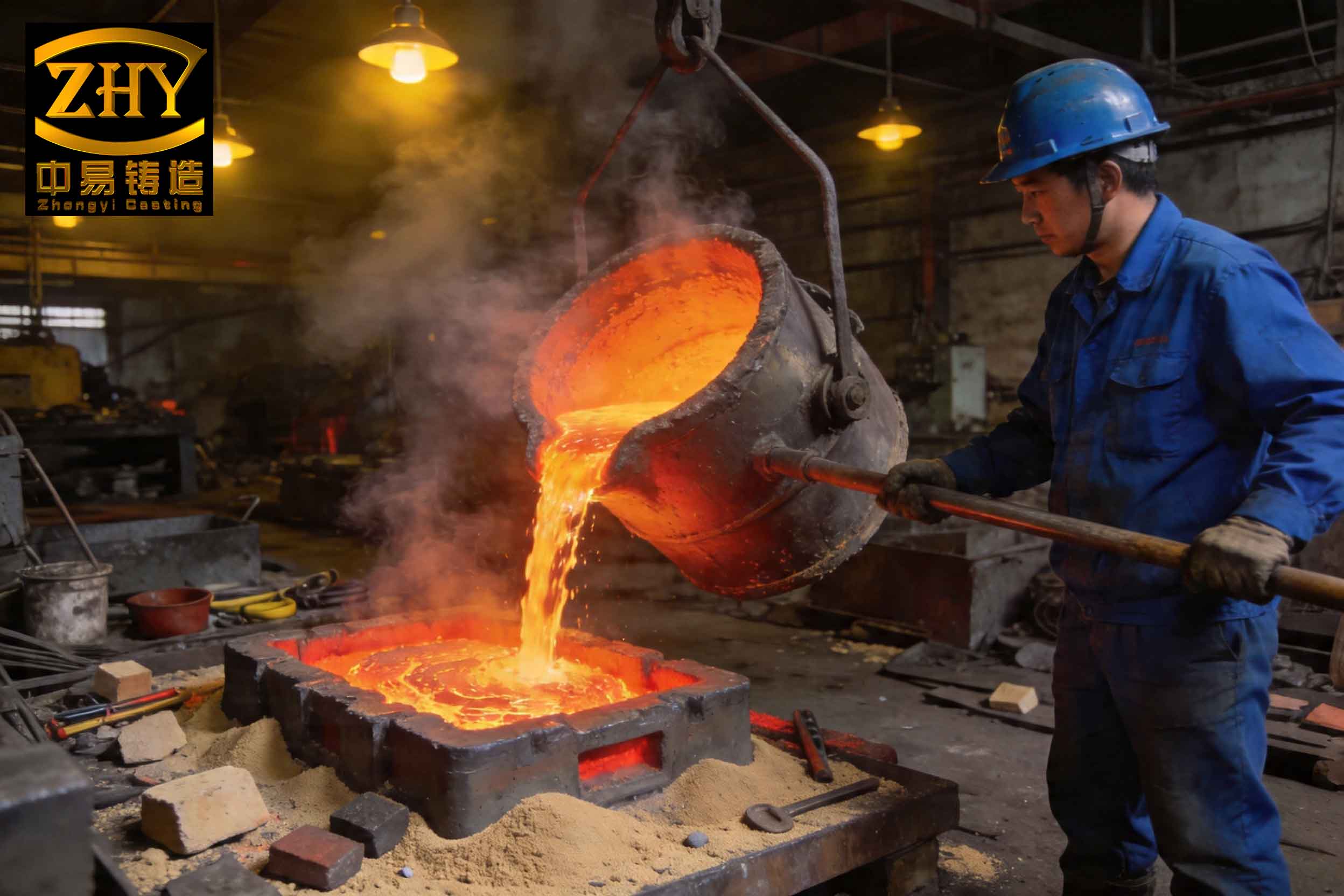
The production environment utilized standard foundry practices. Melting was conducted in a 500 kg resistance furnace, with hexachloroethane serving as the refining agent and a dual-color modification block added at 1 wt.% for grain refinement. The pouring temperature range was maintained between 710°C and 730°C. Molding involved oil-sand cores for the main cavity and green sand with clay binder for the mold, using manual methods. While these conditions are conventional, they set the stage where the slag inclusion defect could originate and propagate if the gating system design was inadequate.
My initial analysis centered on the gating and feeding system design. The casting’s geometry necessitated vertical pouring with the top flange upward to facilitate placement of large risers at the thick boss sections for soundness. A side-gate or slot-gate system was initially deemed suitable for filling the thin web smoothly. Two primary gating schemes were implemented historically: a direct drop system (Scheme A) and a stepped buffer system (Scheme B), both employing a main slot gate. The results were telling: all castings exhibited extensive slag inclusion defects, systematically located in the lower flange and the mid-to-lower regions of the web. This pattern immediately pointed to the gating system as the primary contributor to the slag inclusion defect problem.
To quantify the issue, I examined the fluid dynamics involved. In Scheme A, the metal falls freely from the pouring cup to the inlet sprue with a total drop height (h) of approximately 0.9 m. The impact velocity at the base of the sprue can be estimated using Torricelli’s law for free fall:
$$V = \sqrt{2gh}$$
where \( g \) is the acceleration due to gravity (9.81 m/s²). For h = 0.9 m:
$$V = \sqrt{2 \times 9.81 \times 0.9} \approx 4.2 \text{ m/s}$$
This high velocity, coupled with the abrupt change in direction at the connection to an inclined runner, causes severe turbulence, splashing, and vortex formation. The prolonged exposure of the molten metal to air in this turbulent state generates copious amounts of secondary oxide dross—a primary source for the slag inclusion defect. Furthermore, the erosion of mold surfaces introduces sand inclusions, exacerbating the slag inclusion defect.
Scheme B introduced a horizontal runner at an intermediate height, reducing the direct free-fall height by about 0.3 m. While this mitigated the turbulence somewhat, the inclined runner section still presented a significant drop of 0.545 m, calculated as:
$$h_{\text{inclined}} = h_{\text{total}} – h_{\text{runner}} = 0.9 \text{ m} – 0.3 \text{ m} = 0.6 \text{ m} \text{ (effective vertical component)}$$
The impact velocity at the inclined runner entrance remains substantial, leading to vortex generation and oxide formation. Although the slag inclusion defect severity in the web was reduced compared to Scheme A, the lower flange still showed significant contamination. The data from initial production runs is summarized in Table 1, highlighting the correlation between gating design and slag inclusion defect prevalence.
| Gating Scheme | Number of Castings Produced | Primary Slag Inclusion Defect Locations | Relative Defect Severity (Scale 1-10) | Key Fluid Dynamic Issues |
|---|---|---|---|---|
| Scheme A (Direct Drop) | 12 | Lower Flange and Entire Web | 9 | High impact velocity (~4.2 m/s), severe splashing, strong vortices |
| Scheme B (Stepped Buffer) | 6 | Predominantly Lower Flange | 6 | Reduced but still significant drop, vortex formation in inclined runner |
The fundamental mechanism for slag inclusion defect formation in these scenarios involves the entrainment of oxide films and other non-metallic inclusions due to turbulent flow. The Reynolds number (Re) for flow in the runners can be used to assess turbulence:
$$Re = \frac{\rho V D}{\mu}$$
where \( \rho \) is the density of molten aluminum (~2500 kg/m³), \( V \) is the flow velocity, \( D \) is the hydraulic diameter, and \( \mu \) is the dynamic viscosity (~0.0013 Pa·s near pouring temperature). For a typical runner, with \( D \approx 0.03 \) m and \( V \approx 4 \) m/s, Re exceeds 200,000, indicating highly turbulent flow. Turbulence promotes the breakup of the surface oxide layer and its entrapment within the bulk liquid, directly leading to the slag inclusion defect. Once these inclusions enter the large, flat lower flange or the thin web, the low flow velocities and rapid solidification in these regions prevent their flotation and removal, resulting in permanent defects.
Based on this analysis, I concluded that the key to solving the slag inclusion defect problem lay in radically redesigning the gating system to minimize turbulence, reduce metal fall height, and enhance inclusion removal capabilities. The solution I developed and implemented is a composite gating system integrating a serpentine runner, multiple filters, and a slot gate. This system, depicted conceptually, addresses the shortcomings of the previous designs by introducing multiple stages of flow stabilization and filtration.
The new gating system features a horizontal runner placed at a higher elevation (0.65 m from the base), connected to a serpentine (zigzag) runner with a circular cross-section (diameter 25 mm). This serpentine section dramatically increases the flow path length and introduces repeated changes in direction that dissipate kinetic energy. The flow velocity after the serpentine can be approximated by considering energy losses due to friction and bends. The head loss \( h_f \) in a pipe with multiple bends is given by:
$$h_f = f \frac{L}{D} \frac{V^2}{2g} + \sum K \frac{V^2}{2g}$$
where \( f \) is the Darcy friction factor, \( L \) is the total length, \( D \) is the diameter, and \( K \) are loss coefficients for bends. For a well-designed serpentine, this loss significantly reduces the effective velocity entering the pouring basin or sprue. The metal then passes through a filter placed in the horizontal runner and another within the down-sprue or pouring basin before entering the mold cavity via the slot gate. The gating ratio was carefully calibrated to:
$$F_{\text{sprue}} : F_{\text{runner}} : F_{\text{serpentine}} = 4 : 35 : 10 \approx 1 : 9 : 2.5$$
This ratio ensures progressive flow expansion and pressure reduction, further calming the stream.
The inclusion of ceramic foam filters is a critical element in combating the slag inclusion defect. These filters act as depth filtration media, capturing oxide bi-films and other non-metallic particles. The efficiency of a filter in removing inclusions can be related to the pore size and the Stokes number (Stk) of the particles:
$$Stk = \frac{\rho_p d_p^2 V}{18 \mu D_p}$$
where \( \rho_p \) is the particle density, \( d_p \) is the particle diameter, \( V \) is the approach velocity, and \( D_p \) is the pore diameter. For typical oxide particles in aluminum ( \( d_p \) ~ 10-100 µm), with proper filter selection ( \( D_p \) ~ 1-2 mm) and reduced velocity, Stk becomes sufficiently high for effective impaction and interception, thereby significantly reducing the slag inclusion defect count.
| Parameter | Scheme A (Direct Drop) | Scheme B (Stepped Buffer) | New Composite System |
|---|---|---|---|
| Maximum Free-Fall Height (m) | 0.9 | 0.6 (to inclined runner) | < 0.1 (after serpentine) |
| Estimated Impact Velocity at Gate Inlet (m/s) | ~4.2 | ~3.4 | < 0.5 |
| Turbulence Level (Qualitative) | Very High | High | Low |
| Number of Filtration Stages | 0 (only gravity separation in basin) | 0 | 2 (runner filter + sprue filter) |
| Primary Mechanism for Slag Inclusion Defect Generation | Splashing, Vortexing, Reoxidation | Vortexing in inclined runner | Minimized; residual inclusions filtered |
Implementation of this new system yielded remarkable results. A batch of 24 castings was produced using the composite gating design. X-ray inspection revealed that all castings met the required Class II standards, with no detectable slag inclusion defects in the previously problematic lower flange and web areas. This success conclusively demonstrated that the slag inclusion defect issue was rooted in improper gating dynamics and could be resolved through systematic design optimization.
The broader implications of this study are significant. For large, tall aluminum castings with thin sections and complex geometries, the conventional approach of using simple sprue-runner-gate systems is often inadequate to prevent the slag inclusion defect. My findings advocate for the following principles: First, for skeleton-type or I-beam castings, a composite gating system that combines a calming section (like a serpentine or maze runner) with a slot gate is highly effective. Second, the use of multiple horizontal runners at different levels can be employed to stage the filling and reduce kinetic energy, thereby mitigating the conditions that lead to the slag inclusion defect. Third, the strategic placement of high-quality ceramic foam filters is not merely an option but a necessity for producing high-integrity large aluminum castings. Filters act as a final barrier against the slag inclusion defect, capturing any inclusions generated upstream. Fourth, inclined runners that cause uncontrolled direction changes should be avoided in large castings, as they are potent sources of vortex-driven reoxidation and slag inclusion defect formation.
To further generalize the analysis, I developed a predictive model for the risk of slag inclusion defect formation based on gating parameters. The model incorporates factors such as drop height, runner geometry, and the presence of filters. A simplified risk index (RI) can be expressed as:
$$RI = k_1 \cdot \frac{H}{V_c} + k_2 \cdot \frac{1}{N_f} – k_3 \cdot L_s$$
where \( H \) is the effective metal fall height before entering the mold cavity, \( V_c \) is the critical velocity for oxide film entrainment (typically ~0.5 m/s for aluminum), \( N_f \) is the number of effective filtration stages, \( L_s \) is the length of the flow-stabilizing section (e.g., serpentine), and \( k_1, k_2, k_3 \) are empirical constants. A lower RI value indicates a lower propensity for slag inclusion defect. For the three systems discussed, the calculated RI values would show a clear descending trend from Scheme A to the new composite system, correlating with the observed slag inclusion defect outcomes.
| Gating System | H (m) | N_f | L_s (m) | Assumed Constants: k1=1, k2=2, k3=0.5 | Calculated RI |
|---|---|---|---|---|---|
| Scheme A | 0.9 | 0.5 (poor natural separation) | 0 | RI = 1*(0.9/0.5) + 2*(1/0.5) – 0.5*0 | 5.8 |
| Scheme B | 0.6 | 0.5 | 0 | RI = 1*(0.6/0.5) + 2*(1/0.5) – 0.5*0 | 5.2 |
| New Composite System | 0.1 | 2 (two filters) | 1.5 (serpentine length) | RI = 1*(0.1/0.5) + 2*(1/2) – 0.5*1.5 | 0.2 |
This quantitative approach reinforces the qualitative observations: reducing fall height, adding filtration, and increasing flow path length for stabilization are all effective strategies against the slag inclusion defect.
In conclusion, my investigation into the slag inclusion defect problem in large skeleton-type aluminum castings has yielded clear and actionable insights. The primary cause of the severe slag inclusion defect was the inadequacy of the initial gating systems, which induced high turbulence, splashing, and reoxidation due to excessive metal drop heights. The introduction of a composite gating system, incorporating a serpentine runner for energy dissipation and multiple ceramic foam filters for inclusion capture, proved to be a decisive solution. This system effectively minimized the generation and entrainment of oxides, thereby eliminating the slag inclusion defect. The success underscores that for demanding applications, gating design must prioritize flow tranquility and active filtration to ensure casting soundness. The slag inclusion defect is a controllable phenomenon when the right combination of engineering principles is applied. Future work could focus on optimizing the filter pore size and placement, as well as modeling the exact flow patterns using computational fluid dynamics to further refine the gating design and preemptively address the slag inclusion defect in new casting geometries.
The lessons learned extend beyond this specific case. In the broader context of aluminum casting production, especially for large and complex parts, a proactive approach to gating system design is essential. Engineers must consider the entire journey of the molten metal, from the pouring cup to the farthest recess of the mold cavity, identifying and mitigating every potential source of turbulence and reoxidation that can lead to the slag inclusion defect. By adhering to the principles of controlled filling, kinetic energy management, and rigorous filtration, the incidence of the slag inclusion defect can be dramatically reduced, leading to higher yields, improved mechanical properties, and greater reliability in critical components. The fight against the slag inclusion defect is a continuous one, but with careful analysis and innovative design, it is a battle that can be decisively won.