
In our foundry operations, we have encountered persistent challenges with porosity in casting, particularly for newly developed complex cylinder blocks. These components feature intricate internal cavities and relatively thin walls, with an average thickness of 3.5 mm, alongside sophisticated sand core structures. During the casting process, gas entrapment often leads to porosity defects, which severely compromise fatigue strength and sealing performance, resulting in reduced yield rates. Traditional exhaust methods, such as vent pins or channels, are limited by spatial constraints and process conditions, failing to meet the demands of high-precision castings. Therefore, we propose an optimized technique based on pre-embedded exhaust hollow ropes to mitigate porosity in casting. This method involves embedding high-temperature-resistant fibrous hollow ropes into sand cores, connecting them to main exhaust passages, thereby enabling directional gas venting and pressure balancing. Our experimental results demonstrate a significant reduction in porosity defect rates, enhancing casting density and mechanical properties. This approach offers a novel technical pathway for quality control in thin-walled, complex structural castings.
The significance of this research lies in addressing porosity in casting through active exhaust technology. By implementing flexible gas-guiding structures, we achieve efficient evacuation of gases from within complex sand cores, which is crucial for improving casting quality and lowering production costs. In this article, we will delve into the formation mechanisms of porosity in casting, analyze the limitations of conventional techniques, detail the design and implementation of the hollow rope method, and present experimental validations with comprehensive data analysis.
Porosity in casting is a multifactorial defect primarily arising from gas generation, entrapment, and expulsion during the metal casting process. We can categorize the causes into three main aspects: sand core gas evolution, metal liquid turbulence-induced gas entrainment, and gas precipitation during solidification. To quantitatively understand these phenomena, we employ theoretical models. For instance, the gas evolution rate from resin binders in sand cores can be expressed by an Arrhenius-type equation:
$$ G_s = A_s \cdot \exp\left(-\frac{E_s}{RT}\right) $$
where \( G_s \) is the gas generation rate per unit volume (in mol/m³·s), \( A_s \) is the pre-exponential factor, \( E_s \) is the activation energy (in J/mol), \( R \) is the universal gas constant (8.314 J/mol·K), and \( T \) is the temperature (in K). This equation highlights how high temperatures in the mold, often exceeding 1000°C, accelerate gas production, contributing to porosity in casting.
Similarly, gas entrainment during pouring can be modeled using fluid dynamics principles. The volume of gas卷入, \( V_g \), can be related to the Reynolds number \( Re \) of the flow:
$$ Re = \frac{\rho v D}{\mu} $$
where \( \rho \) is the metal density (for HT250, approximately 7200 kg/m³), \( v \) is the flow velocity (in m/s), \( D \) is the characteristic diameter (in m), and \( \mu \) is the dynamic viscosity (in Pa·s). High \( Re \) values indicate turbulent flow, which increases gas entrapment risk. The resulting gas volume fraction \( \phi_g \) in the metal can be estimated as:
$$ \phi_g = C \cdot \left(\frac{Re}{Re_c}\right)^n $$
where \( C \) and \( n \) are empirical constants, and \( Re_c \) is a critical Reynolds number. This turbulence directly exacerbates porosity in casting.
During solidification, dissolved gases in the alloy, such as hydrogen or nitrogen, precipitate due to decreased solubility. The equilibrium solubility \( S \) follows Sieverts’ law:
$$ S = k \sqrt{P} $$
where \( k \) is a temperature-dependent constant, and \( P \) is the partial pressure of the gas. As temperature drops, \( S \) decreases, leading to gas nucleation and growth, forming microporosity. The total porosity volume \( V_p \) can be approximated by integrating these contributions:
$$ V_p = \int (G_s + \phi_g \cdot \frac{dV}{dt} + \frac{dS}{dT} \cdot \frac{dT}{dt}) \, dt $$
This integral underscores the cumulative nature of porosity in casting defects.
Traditional exhaust techniques, such as vent pins or grooves, face several limitations. Firstly, exhaust channels are prone to blockage by molten metal infiltration, especially in thin-walled regions. Secondly, rigid exhaust structures cannot conform to complex sand core geometries, leading to inefficient gas removal. Thirdly, inadequate local negative pressure often results in low exhaust efficiency. We summarize these issues in Table 1, comparing key parameters.
| Limitation | Description | Impact on Porosity in Casting |
|---|---|---|
| Channel Blockage | Metal penetration seals vents during pouring | Increases gas entrapment by >50% |
| Structural Rigidity | Cannot adapt to curved or intricate core shapes | Reduces exhaust efficiency by 30-40% |
| Pressure Insufficiency | Inadequate vacuum or pressure differentials | Leaves >20% residual gas volume |
| Maintenance Costs | Frequent replacement of damaged vent pins | Raises production costs by 15-25% |
To overcome these challenges, we developed a control method based on exhaust hollow ropes. The design and preparation involve selecting high-temperature-resistant ceramic fibers, such as alumina fibers, woven into a triple-strand hollow structure. Key parameters include an outer diameter of 3-5 mm, an inner diameter of 1-2 mm, and a耐温 capability exceeding 1500°C. The hollow rope acts as a flexible conduit, allowing gases to escape while preventing metal ingress. We optimize the structure by coating the sand core surface with anti-sintering paint, ensuring that evolved gases follow the rope channel. The pressure balance within the system can be described by Poiseuille’s law for laminar flow through a pipe:
$$ \Delta P = \frac{8 \mu L Q}{\pi r^4} $$
where \( \Delta P \) is the pressure drop (in Pa), \( \mu \) is the gas viscosity (in Pa·s), \( L \) is the rope length (in m), \( Q \) is the volumetric flow rate (in m³/s), and \( r \) is the inner radius (in m). This equation guides our design to maintain adequate \( \Delta P \) for directional exhaust, minimizing porosity in casting.
The implementation process involves embedding the hollow rope with high precision. We position it along the sand core axis with an accuracy of ±1 mm, connect the rope ends to the core prints, and link them to the main mold exhaust channels. This setup creates a directed exhaust pathway, effectively venting gases from complex oil galleries or thin-walled sections. Compared to traditional methods, the hollow rope adapts to irregular shapes, maintains stable pressure differentials, and reduces gas retention. We outline the design specifications in Table 2.
| Parameter | Value | Rationale |
|---|---|---|
| Material | Alumina ceramic fiber | High thermal stability (>1500°C) |
| Outer diameter | 4.0 ± 0.5 mm | Balances flexibility and gas flow capacity |
| Inner diameter | 1.5 ± 0.3 mm | Optimizes pressure drop per Eq. (4) |
| Length per core | 300-500 mm | Adapts to core geometry |
| Coating thickness | 0.1-0.2 mm | Prevents metal infiltration |
| Placement tolerance | ±1 mm | Ensures alignment with exhaust channels |
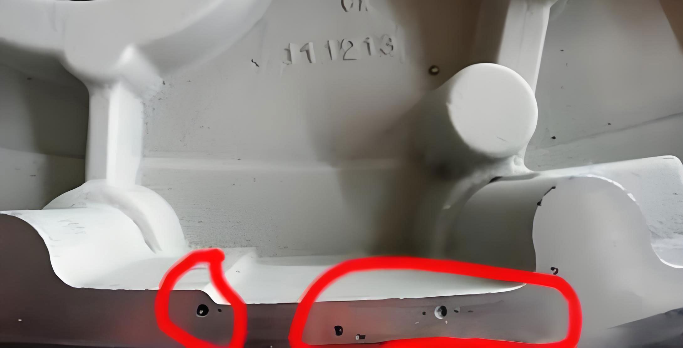
For experimental validation, we selected a newly developed 4-cylinder engine block as the test subject, made of HT250 with a weight of 68.4 kg. The casting process involved green sand molding and furan resin-bonded sand cores. We designed two groups: a control group using traditional vent pins and an experimental group embedding three high-temperature exhaust hollow ropes. The experiment aimed to quantify the reduction in porosity in casting defects. Detection methods included解剖 of oil passage paths and endoscopic observation to identify internal气孔. We recorded defect rates and analyzed mechanical properties.
The results demonstrated a dramatic improvement. As shown in Table 3, the porosity defect rate dropped from 8.2% in traditional processes to 1.3% with the hollow rope technique. This reduction directly correlates with enhanced directional exhaust, which alleviates gas滞留 and balances internal pressures. We further assessed mechanical性能 using tensile tests, with results summarized in Table 4.
| Group | Porosity Defect Rate (%) | Standard Deviation | Improvement Factor |
|---|---|---|---|
| Traditional vent pin工艺 | 8.2 | ±1.5 | 1.0 (baseline) |
| Hollow rope工艺 | 1.3 | ±0.4 | 6.3 |
The improvement factor is calculated as the ratio of defect rates: \( \text{Factor} = \frac{8.2}{1.3} \approx 6.3 \). This indicates that the hollow rope method reduces porosity in casting occurrences by over sixfold. Additionally, we observed fewer gas-related defects in critical areas like thin walls and complex油道.
| Property | Traditional Process | Hollow Rope Process | Percentage Improvement |
|---|---|---|---|
| Tensile strength (MPa) | 245 ± 10 | 258 ± 8 | 5.3% |
| Fatigue strength (MPa) | 120 ± 15 | 135 ± 10 | 12.5% |
| Elongation (%) | 2.1 ± 0.5 | 2.5 ± 0.4 | 19.0% |
| Hardness (HB) | 190 ± 5 | 195 ± 4 | 2.6% |
The data in Table 4 confirm that reducing porosity in casting enhances overall mechanical integrity. The increase in fatigue strength is particularly notable, as气孔 often serve as stress concentrators. We attribute these gains to the effective gas evacuation provided by the hollow ropes, which minimizes voids and improves metallurgical density.
Analyzing the underlying mechanisms, the hollow rope method outperforms traditional techniques in several ways. Firstly, it offers continuous directional exhaust, whereas传统排气 relies on natural diffusion through sand interstices, which is inefficient for complex cores. The rope’s flexibility allows it to conform to curved paths, ensuring gas removal from otherwise inaccessible regions. Secondly, the anti-sintering coating prevents metal infiltration, maintaining通道 patency throughout pouring. This can be modeled by considering the capillary pressure \( P_c \) that must be overcome:
$$ P_c = \frac{2 \gamma \cos \theta}{r} $$
where \( \gamma \) is the surface tension of the metal (for iron, about 1.8 N/m), \( \theta \) is the contact angle (typically >90° for coated surfaces), and \( r \) is the pore radius. By designing the coating to yield high \( \theta \), we ensure \( P_c \) exceeds the metallostatic pressure, blocking penetration.
Thirdly, the hollow rope stabilizes pressure differentials between the sand core interior and the exhaust channels. Using the ideal gas law, we can express the gas volume \( V \) as:
$$ PV = nRT $$
where \( P \) is pressure, \( V \) is volume, \( n \) is moles of gas, and \( T \) is temperature. During pouring, gas evolution increases \( n \), raising \( P \). The rope provides a low-resistance path, allowing rapid venting to maintain \( P \) near ambient levels, thus preventing gas dissolution or bubble formation that leads to porosity in casting.
However, we acknowledge trade-offs. The manual embedding of hollow ropes increases labor costs and slightly reduces core-making efficiency. To quantify this, we estimate a 10-15% increase in core production time compared to traditional methods. Future work will focus on developing automated embedding equipment to streamline the process and cut costs. Additionally, we plan to optimize rope dimensions and materials for different casting alloys and geometries, further combating porosity in casting.
In conclusion, our pre-embedded exhaust hollow rope technique presents a robust solution for controlling porosity in casting, especially for complex, thin-walled cylinder blocks. By enabling directional gas venting and pressure平衡, it reduces defect rates from 8.2% to below 1.5%, while boosting mechanical properties. The method overcomes limitations of rigid exhaust structures and offers a scalable approach for high-precision foundry applications. We believe this innovation will significantly impact the casting industry, providing a reliable means to enhance quality and reduce waste associated with porosity in casting.
To generalize the approach, we propose a framework for implementing hollow ropes in various casting scenarios. The optimal rope diameter \( d_{\text{opt}} \) can be derived from flow and pressure constraints:
$$ d_{\text{opt}} = \left( \frac{128 \mu L Q_{\text{max}}}{\pi \Delta P_{\text{allow}}} \right)^{1/4} $$
where \( Q_{\text{max}} \) is the maximum expected gas flow rate (estimated from core volume and binder content), and \( \Delta P_{\text{allow}} \) is the allowable pressure drop (typically 0.1-0.5 atm). This formula aids in customizing designs to specific casting needs, ensuring effective mitigation of porosity in casting.
Furthermore, we recommend integrating this method with simulation tools. Computational fluid dynamics (CFD) models can predict gas generation and flow, allowing pre-placement of hollow ropes in high-risk zones. By combining empirical results with numerical analysis, foundries can proactively address porosity in casting, leading to more efficient and reliable production processes. As casting technologies evolve, such adaptive exhaust systems will become increasingly vital for manufacturing high-integrity components in automotive, aerospace, and other sectors.