
In my extensive experience with full mold casting (FMC), a subset of expendable pattern casting (EPC) technologies, I have focused on producing large-scale machine tool components such as beds, columns, and saddles from gray iron. These castings, ranging from 500 to 5,000 kg in weight with wall thicknesses between 15 and 100 mm, are critical for industrial machinery. However, a persistent challenge has been the formation of carbonaceous slag inclusions—black, slag-like defects—primarily on the top and upper-side surfaces after machining. These slag inclusions not only compromise surface integrity, causing wrinkles and carbon deposits, but also reduce the structural density of the castings, leading to significant scrap rates. Historically, in our production, slag inclusions alone accounted for approximately 8% of the total scrap, contributing to an overall scrap rate of 15–16%. This article details my first-person investigation into the root causes, experimental analysis, and effective control methods for mitigating these detrimental slag inclusions in FMC-produced gray iron castings.
The slag inclusions in FMC are intrinsically linked to the thermal degradation of expanded polystyrene (EPS) patterns, which are typically machined from foam boards with a density of 18 g/L. During pouring, molten iron advances and replaces the EPS pattern, which undergoes pyrolysis. This process occurs in two stages: primary breakdown of the polystyrene chain into monomers like styrene, dimers, trimers, and toluene, followed by secondary decomposition into smaller molecules such as benzene and ethylbenzene. The extent of secondary decomposition is temperature-dependent; insufficient decomposition at lower temperatures yields viscous, tarry liquid residues. These residues accumulate at the coating-casting interface, forming a carbon-rich film that poorly wets the iron, leading to surface defects and, when entrapped within the metal, internal slag inclusions. The relationship between pyrolysis products and temperature is crucial, as higher temperatures promote gaseous products, reducing liquid residue. This can be modeled by the following expression for the mass fraction of liquid residue, $L(T)$, as a function of temperature $T$:
$$ L(T) = L_0 \cdot e^{-k(T – T_0)} $$
where $L_0$ is the initial liquid potential, $k$ is a rate constant dependent on EPS composition, and $T_0$ is a reference temperature. In practice, the temperature drop along the flow path—especially in bottom-gated systems used to avoid back-pressure issues—exacerbates slag inclusion formation in top sections and remote areas from the ingates.
To systematically evaluate the influence of key process parameters on slag inclusion severity, I designed and conducted an orthogonal experiment with four factors at two levels: pouring temperature, pouring time (via choke size), coating thickness, and EPS density. The test casting was a stepped block with dimensions 300 mm × 300 mm and thicknesses incrementing from 20 mm to 80 mm, as illustrated in the design. A total of 16 patterns were grouped and processed under controlled conditions. The experimental matrix is summarized in Table 1.
| Group | Pattern ID | Pouring Temperature (°C) | Choke Diameter (mm) | Coating Thickness (mm) | EPS Density (g/L) |
|---|---|---|---|---|---|
| A | #1 | 1430 | 60 | 1.0 ± 0.2 | 21 |
| #2 | 1430 | 60 | 2.0 ± 0.2 | 21 | |
| #3 | 1430 | 60 | 1.0 ± 0.2 | 18 | |
| #4 | 1430 | 60 | 2.0 ± 0.2 | 18 | |
| B | #5 | 1430 | 80 | 1.0 ± 0.2 | 21 |
| #6 | 1430 | 80 | 2.0 ± 0.2 | 21 | |
| #7 | 1430 | 80 | 1.0 ± 0.2 | 18 | |
| #8 | 1430 | 80 | 2.0 ± 0.2 | 18 | |
| C | #9 | 1370 | 60 | 1.0 ± 0.2 | 21 |
| #10 | 1370 | 60 | 2.0 ± 0.2 | 21 | |
| #11 | 1370 | 60 | 1.0 ± 0.2 | 18 | |
| #12 | 1370 | 60 | 2.0 ± 0.2 | 18 | |
| D | #13 | 1370 | 80 | 1.0 ± 0.2 | 21 |
| #14 | 1370 | 80 | 2.0 ± 0.2 | 21 | |
| #15 | 1370 | 80 | 1.0 ± 0.2 | 18 | |
| #16 | 1370 | 80 | 2.0 ± 0.2 | 18 |
After pouring, the blocks were cleaned and subjected to sequential machining cuts of 5 mm, 10 mm, and 15 mm on the top surface to expose and quantify slag inclusions. Defect frequency, location, and area percentage were recorded, supplemented by penetrant testing (PT) to determine depth. The results revealed several critical insights. First, all blocks exhibited slag inclusions to some degree after a 5 mm cut, confirming that slag inclusions are inherent in FMC without mitigation measures. Second, after a 10 mm cut, the severity—measured as defect area percentage—varied significantly. The best-performing blocks (#3, #7, #2, #4, #5, #6) had area percentages ranging from 3.3% to 10%, while others reached up to 28.7%. This indicated that higher pouring temperature (1430°C), slower pouring (smaller choke), and thinner coatings reduced slag inclusion severity. Third, after a 15 mm cut, blocks poured at 1430°C showed no visible slag inclusions on the surface, but PT detected subsurface defects up to 10 mm deep at edges, implying that slag inclusions penetrate shallower in high-temperature pours. Fourth, a strong correlation emerged between wall thickness and slag inclusion occurrence: thicker sections (60 mm and 80 mm) hosted defects more frequently, suggesting that residual liquid slag accumulates proportionally to thermal mass. This relationship can be expressed as:
$$ S \propto \int_{0}^{t} \frac{dL}{dT} \cdot \frac{dT}{dx} \, dx $$
where $S$ is the slag inclusion propensity, $t$ is the wall thickness, $L$ is liquid residue, $T$ is temperature, and $x$ is distance from the ingate. Essentially, thicker walls experience greater temperature drops, leading to more incomplete pyrolysis and higher slag inclusion risk.
Based on these findings, I implemented a series of targeted improvements to control slag inclusions. The gating system was redesigned from a single-point bottom gate to a multi-point bottom gating system with strategically placed ingates near thick sections to ensure uniform thermal distribution and reduce temperature gradients. A choke with a cross-sectional area 0.8–0.9 times that of the sprue was incorporated near the sprue to stabilize flow and trap early slag. The area ratios were standardized: sprue : runner : ingate = 1 : (1.3–1.5) : (3–5). Sprue diameters were scaled with casting weight: 70 mm for 500–1000 kg, 80 mm for 1000–2000 kg, and 100 mm for over 2000 kg. Additionally, machining allowances were increased by 10–15 mm on top and upper-side surfaces to provide extra material for removal during rough machining, effectively eliminating near-surface slag inclusions. For slag collection, spherical risers with diameters of 60–100 mm were placed atop the casting and at thick section ends to capture cold metal and pyrolysis residues. The optimal riser diameter $D_r$ can be estimated using the modulus method:
$$ D_r = \frac{6 \cdot M_c}{\pi} $$
where $M_c$ is the casting modulus at the hot spot. Process controls were tightened: pouring temperature was raised from 1380 ± 10°C to 1440 ± 10°C to enhance EPS gasification, and coatings with high refractoriness and permeability were adopted. Furthermore, for thick-walled regions exceeding 60 mm, EPS patterns were partially hollowed out to reduce foam volume, thereby decreasing liquid residue generation. This approach aligns with the principle that slag inclusions are minimized when the foam mass per unit volume is reduced, as described by:
$$ m_{foam} = \rho_{EPS} \cdot V_{foam} $$
where reducing $V_{foam}$ directly lowers $m_{foam}$ and subsequent residue.
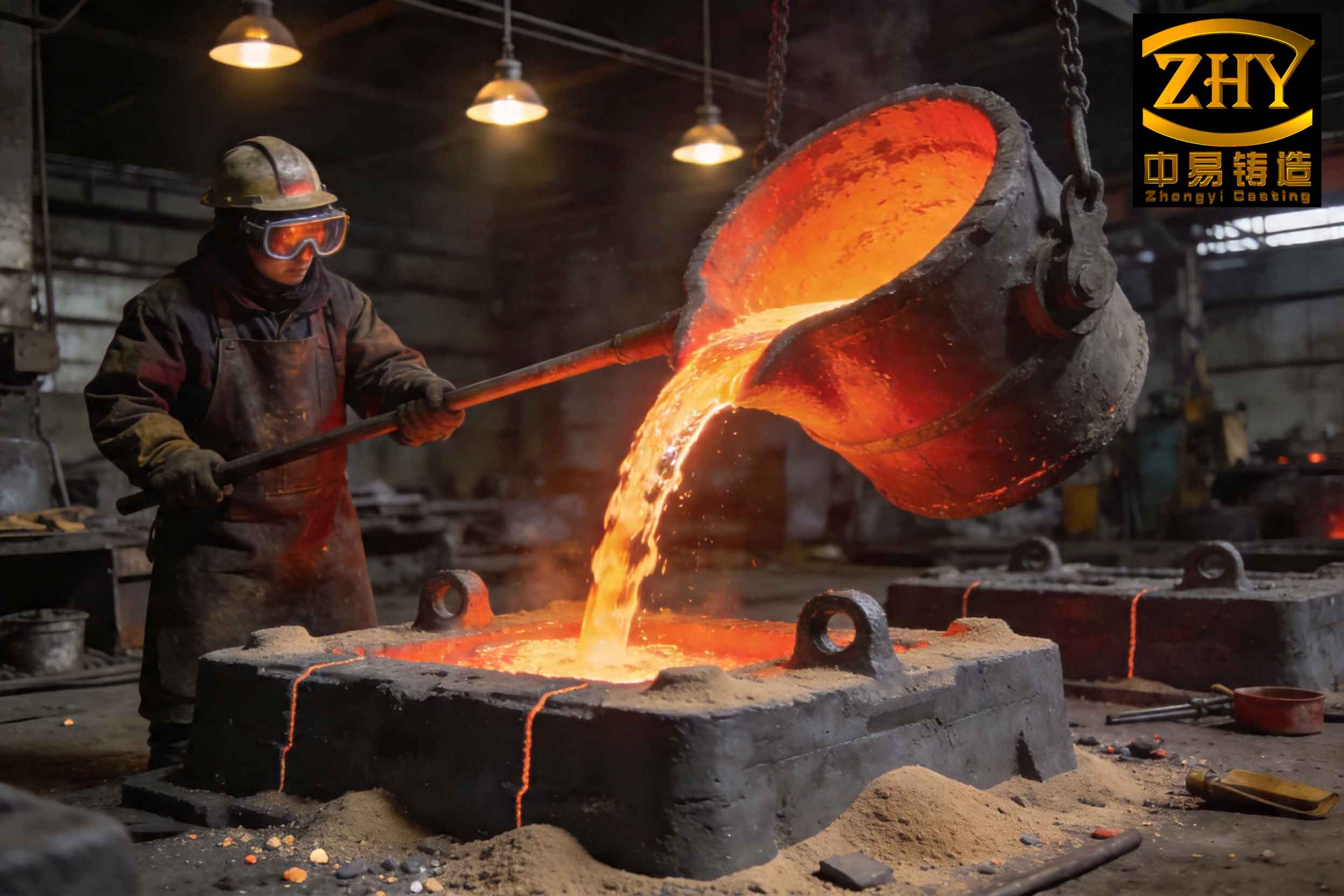
The effectiveness of these modifications was profound. Over sustained production, monthly output reached 240–250 tons, with the overall scrap rate dropping to 10–11% and the slag inclusion-specific scrap rate falling below 4%. This marked improvement underscores the importance of a holistic approach integrating gating design, thermal management, and pattern optimization. To further elucidate the factors affecting slag inclusions, I developed a comprehensive summary table based on the experimental data and operational adjustments, as shown in Table 2.
| Factor | Effect on Slag Inclusions | Optimal Range/Value | Mechanism |
|---|---|---|---|
| Pouring Temperature | Inverse correlation: higher temperature reduces slag inclusions | 1440 ± 10°C | Promotes complete EPS pyrolysis, minimizing liquid residue formation. |
| Pouring Time (Choke Size) | Slower pouring (smaller choke) reduces slag inclusions | Choke area = 0.8–0.9 × sprue area | Allows better heat retention and controlled metal advance, reducing thermal drop. |
| Coating Thickness | Thinner coatings reduce slag inclusions | 1.0 ± 0.2 mm | Enhances gas escape, preventing residue entrapment at the interface. |
| EPS Density | Lower density reduces slag inclusions marginally | 18 g/L | Decreases total foam mass, thus less residue per unit volume. |
| Wall Thickness | Direct correlation: thicker walls increase slag inclusions | Local hollowing for >60 mm sections | Greater thermal mass leads to steeper temperature gradients and incomplete pyrolysis. |
| Gating Design | Multi-point bottom gating reduces slag inclusions | Sprue : runner : ingate = 1 : 1.4 : 4 | Improves thermal uniformity and reduces cold spots at the top. |
| Riser Design | Spherical risers collect slag inclusions | Diameter 60–100 mm | Acts as a reservoir for slag and cold metal, preventing entrainment. |
| Machining Allowance | Increased allowance eliminates near-surface slag inclusions | 10–15 mm extra on top surfaces | Provides a buffer for machining away defect-prone layers. |
Beyond these practical measures, I delved into theoretical modeling to predict slag inclusion formation. The rate of liquid residue generation $R_{res}$ during EPS decomposition can be approximated by an Arrhenius-type equation:
$$ R_{res} = A \cdot e^{-E_a / (R T)} \cdot [EPS] $$
where $A$ is a pre-exponential factor, $E_a$ is the activation energy for pyrolysis, $R$ is the gas constant, $T$ is the local temperature, and $[EPS]$ is the foam concentration. Integrating this over the casting volume and time yields the total residue potential, which must be minimized through process controls. Additionally, the fluid dynamics of slag entrapment can be described by Stokes’ law, where the settling velocity $v_s$ of slag particles in molten iron is:
$$ v_s = \frac{2 g r^2 (\rho_{slag} – \rho_{iron})}{9 \eta} $$
where $g$ is gravity, $r$ is particle radius, $\rho$ denotes densities, and $\eta$ is the viscosity of iron. Since carbonaceous slag particles are often lightweight and viscous, they tend to float upward, explaining their prevalence on top surfaces. However, in thick sections with slow cooling, they may become trapped if the metal solidifies before they rise fully. Therefore, accelerating solidification through chilling or optimizing riser placement is beneficial.
In practice, the interaction between these factors is complex. To guide foundry engineers, I formulated a slag inclusion index $I_{slag}$ that combines key variables:
$$ I_{slag} = \frac{k_1 \cdot t^{2} \cdot \rho_{EPS}}{k_2 \cdot T_{pour} \cdot v_{flow} \cdot \delta_{coat}} $$
where $t$ is wall thickness, $\rho_{EPS}$ is foam density, $T_{pour}$ is pouring temperature, $v_{flow}$ is flow velocity (inversely related to pouring time), $\delta_{coat}$ is coating thickness, and $k_1$, $k_2$ are empirical constants. A lower index indicates reduced slag inclusion risk, aligning with our experimental observations. For instance, increasing $T_{pour}$ or decreasing $t$ (via hollowing) lowers $I_{slag}$, directly mitigating slag inclusions.
Looking forward, continuous monitoring and adaptation are essential. Real-time thermal imaging during pouring could help identify cold zones prone to slag inclusions, allowing dynamic adjustments. Moreover, alternative pattern materials like polymethyl methacrylate (PMMA) or starch-based foams, which decompose more cleanly at lower temperatures, may further reduce slag inclusions, though cost and availability must be considered. In our context, sticking to EPS with optimized parameters proved sufficient.
In conclusion, slag inclusions in FMC machine tool castings are a multifaceted defect driven by incomplete EPS pyrolysis, exacerbated by thermal gradients and thick sections. Through rigorous experimentation, I established that high pouring temperatures, controlled slow pouring, thin coatings, and multi-point gating are paramount. Implementing these, along with strategic risers, increased machining allowances, and pattern hollowing, slashed the slag inclusion scrap rate from 8% to under 4%. This holistic strategy not only enhances casting quality but also boosts productivity, affirming that a deep understanding of process physics is key to mastering full mold casting. As I continue to refine these methods, the goal remains clear: to produce flawless gray iron castings where slag inclusions are a relic of the past.