
In the context of automotive lightweighting and increasing demands for engine performance, the wall thickness of engine cylinder blocks has been progressively reduced to 3.5 mm, with material grades upgraded from HT250 to HT300. While meeting structural and cost requirements, these changes have amplified shrinkage porosity risks, leading to leakage failures during engine testing and post-market use. This article analyzes the root causes and proposes systematic solutions.
1. Technical Specifications and Failure Modes
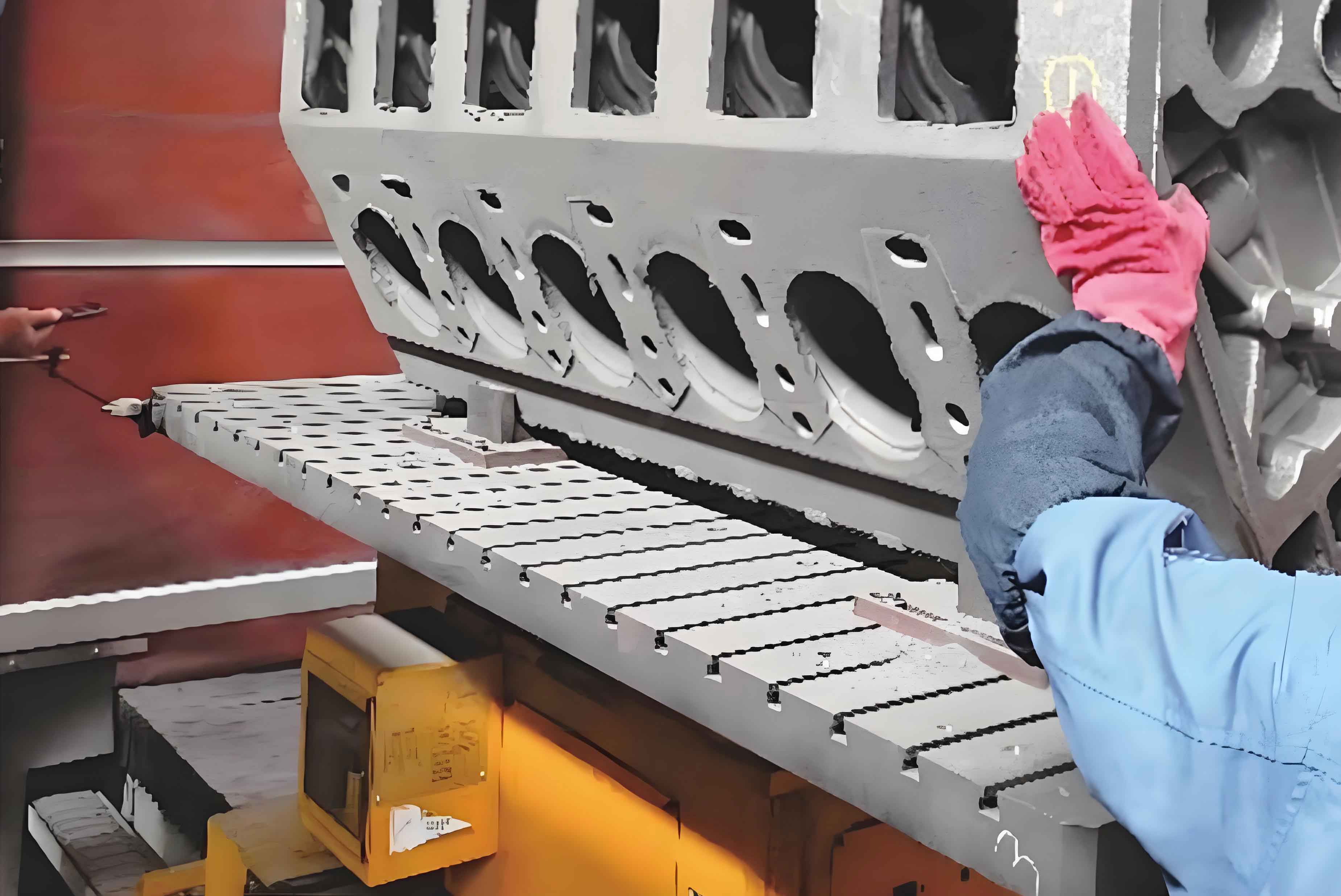
The HT300 engine cylinder block features a minimum wall thickness of 3.8 mm, produced using cold-box core shooting and semi-automatic pouring. Key specifications include:
| Parameter | Requirement |
|---|---|
| Graphite Structure | A-type ≥70%, B-type <20% |
| Pearlite Content | ≥90% |
| Tensile Strength | ≥220 MPa |
| Hardness | 187-241 HBW |
Chemical composition requirements are shown in Table 1:
| C | Si | Mn | Cu | Cr | Sn |
|---|---|---|---|---|---|
| 3.28-3.32 | 1.60-1.70 | 0.70-0.90 | 0.50-0.70 | 0.25-0.35 | 0.04-0.07 |
2. Shrinkage Porosity Mechanism
The primary leakage mechanism in engine cylinder blocks stems from shrinkage porosity at bolt holes and thick sections. The solidification time (t) for these regions can be estimated using Chvorinov’s rule:
$$ t = k \left( \frac{V}{A} \right)^2 $$
Where:
k = solidification constant
V = volume of thick section
A = cooling surface area
For bolt hole regions with 5-6 mm thickness, calculations show 38% longer solidification time compared to 3.8 mm walls, creating favorable conditions for shrinkage defects.
3. Key Improvement Strategies
3.1 Metallurgical Optimization
Adjustments to carbon equivalent (CE) and alloy content:
$$ CE = C + \frac{Si}{3} + \frac{P}{3} $$
Modified parameters:
| Parameter | Original | Adjusted |
|---|---|---|
| C | 3.28-3.30% | 3.30-3.32% |
| Cr | 0.30-0.35% | 0.25-0.30% |
| CE | 3.90-4.00 | 4.02-4.10 |
3.2 Charge Material Reformulation
Revised charge composition:
| Material | Original (%) | Adjusted (%) |
|---|---|---|
| Pig Iron | 0-25 | 15-30 |
| Scrap Steel | 30-70 | 20-50 |
| Returns | 30-70 | 30-60 |
3.3 Tellurium Coating Application
The tellurium coating acts as chemical chill, with effectiveness quantified by:
$$ Q = \frac{\alpha \cdot \rho \cdot c_p}{k} \cdot \Delta T $$
Where:
α = thermal diffusivity
ρ = density
cp = specific heat
k = thermal conductivity
ΔT = temperature gradient
3.4 Design Modifications
Wall thickness optimization at critical sections:
| Location | Original (mm) | Modified (mm) |
|---|---|---|
| Bolt Hole Adjacent Area | 4.2 | 5.0 |
| Oil Gallery Junction | 3.8 | 4.5 |
4. Results and Discussion
The implemented solutions achieved significant quality improvements:
| Model | Pre-Improvement Rejection (%) | Post-Improvement (%) |
|---|---|---|
| 493 Series | 6.3 | 0.8 |
| PUMA Series | 10.29 | 0.89 |
Microstructural analysis confirmed the effectiveness of tellurium coating in promoting chill formation:
$$ \text{Chill Depth} = 0.15 \cdot \sqrt{t} \cdot (1 + 0.01\cdot Te_{conc}) $$
Where:
t = solidification time (s)
Teconc = tellurium concentration (wt.%)
5. Conclusion
Through systematic optimization of metallurgical parameters, charge composition, localized chilling, and design enhancements, shrinkage porosity defects in thin-wall engine cylinder blocks were effectively controlled. The solutions demonstrate the importance of integrated approach combining foundry engineering and design modification for high-performance engine components.