
The advancement of modern urban rail transit systems is inextricably linked to the reliable performance of their core components. Among these, the traction motor housing represents a critical structural element, responsible for protecting and supporting the internal electromagnetic assembly. These housings are typically produced as shell castings using nodular iron (ductile iron), a material chosen for its excellent combination of strength, ductility, and castability. The development of such castings presents unique challenges due to their complex geometry, varying wall thicknesses, and stringent quality requirements, necessitating a meticulous approach to casting process design.
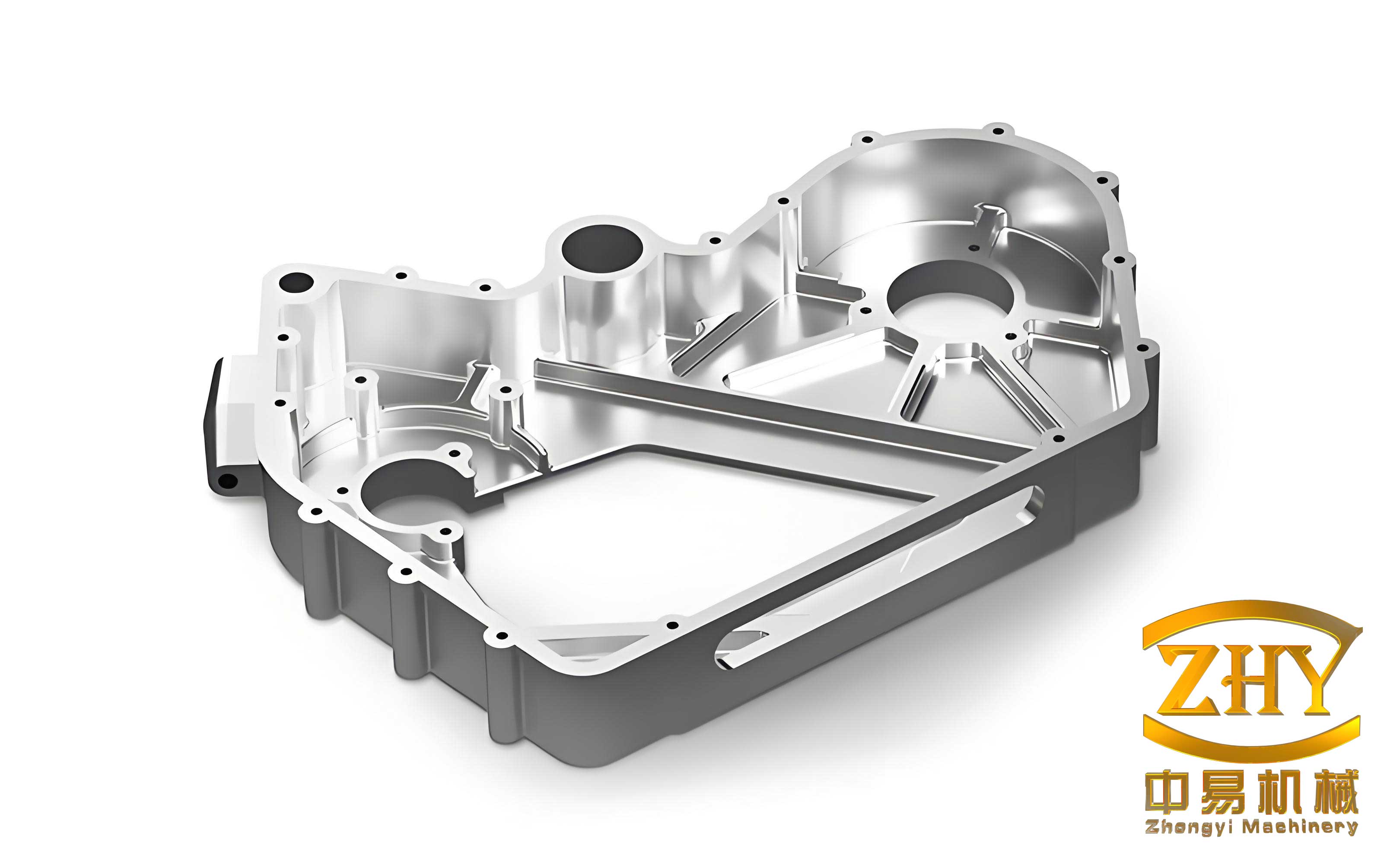
The specific shell casting under consideration is characterized by a thin-walled, barrel-like structure. Key dimensions are approximately 760 mm in length, 500 mm in width, and 580 mm in height, with a final casting weight near 160 kg. The nominal wall thickness of the main barrel section is 10 mm, but the design incorporates several reinforcing ribs, mounting brackets, and connection boxes, leading to localized thick sections up to 90 mm. This disparity in wall thickness creates isolated thermal masses, or hot spots, which are primary locations for potential shrinkage porosity if not properly addressed during solidification. The material specification is QT500-7 (equivalent to EN-GJS-500-7), requiring a minimum tensile strength of 500 MPa, a yield strength of 320 MPa, and 7% elongation. Furthermore, the casting must undergo X-ray inspection, with acceptance criteria demanding higher quality levels (e.g., Level 2) in critically stressed areas.
Casting Challenges and Initial Process Definition
The fundamental challenge in producing sound shell castings of this nature lies in controlling the solidification pattern. The identified hot spots are typically located at the junctions where internal ribs, mounting lugs, or cable boxes meet the primary barrel wall. These areas act as thermal nodes, remaining liquid longer than the surrounding thin sections. Without directional solidification towards a feeding source, shrinkage defects will form in these last-to-freeze zones.
The first step in process design is determining the optimal pouring position and mold parting line. Two principal orientations were evaluated:
- Vertical Orientation: The barrel axis is placed vertically. This allows for a bottom-gating system, promoting tranquil mold filling. It can be advantageous for feeding thermal centers along the internal ribs but makes feeding the side-mounted brackets extremely difficult, often requiring a complex array of side risers.
- Horizontal Orientation: The barrel axis is placed horizontally, with the mold parted along the vertical plane of the axis (HALF split). This orientation simplifies the molding process, reduces the number of cores required compared to the vertical method, and positions major hot spots like mounting brackets near the cope or along the parting line, making them more accessible for riser placement.
For this motor housing shell casting, the horizontal orientation was selected. This decision prioritizes the manageability of feeding the most problematic thick sections associated with the functional brackets.
Rigorous Gating System Design
A properly designed gating system is essential for achieving a clean, defect-free filling sequence. For horizontally-poured shell castings, the iron must be introduced smoothly to avoid turbulence, oxide formation, and sand erosion. The selected design employs a gating system along the parting plane, with two ingates introducing metal into the cavity at opposing sides of the barrel wall. The key parameters are calculated systematically.
1. Pouring Time (t): The optimal pouring time is critical to ensure the mold fills completely before solidification begins in the thin sections, while also maintaining an adequate metallostatic head for feeding. An empirical formula is used:
$$t = K \sqrt{G}$$
where \( t \) is the pouring time in seconds, \( G \) is the total mass of metal in the mold (including casting, gating, and risers) in kg, and \( K \) is an empirical coefficient dependent on casting thickness. For medium-section iron castings, \( K \) is typically between 1.8 and 2.0. With a total metal mass \( G \) of approximately 180 kg, and selecting \( K = 1.85 \), the calculated pouring time is:
$$t = 1.85 \times \sqrt{180} \approx 25 \text{ seconds}$$
2. Minimum Fill Rate (V): The fill rate, or the upward velocity of the metal in the mold cavity, must be sufficient to prevent mistruns in the upper sections. It is verified using:
$$V = \frac{C}{t}$$
where \( V \) is the fill rate in cm/s and \( C \) is the height of the casting in the poured position in cm. With \( C = 48 \) cm, the fill rate is:
$$V = \frac{48}{25} = 1.92 \text{ cm/s}$$
This value falls within the acceptable range for nodular iron castings of this wall thickness.
3. Choke Area (Schoke): The choke, typically the smallest cross-sectional area in the gating system (often at the base of the sprue or in the ingates), regulates the flow rate. Its area is calculated using the fluid flow equation:
$$S_{\text{choke}} = \frac{G}{0.31 \mu t \sqrt{H_p}}$$
where \( \mu \) is the total friction factor (accounting for losses in the system, typically 0.45-0.55 for iron), and \( H_p \) is the effective metallostatic pressure head in cm. For a horizontally-poured casting with top gating, \( H_p \) is taken as the height from the choke to the top of the cope cavity. With \( \mu = 0.48 \) and \( H_p = 35 \) cm, the initial calculation yields:
$$S_{\text{choke}} = \frac{180}{0.31 \times 0.48 \times 25 \times \sqrt{35}} \approx 8.5 \text{ cm}^2$$
Based on practical experience to ensure adequate flow and account for minor losses, this area is often increased. A final choke area of \( 12 \text{ cm}^2 \) was selected.
4. Gating Ratio & Dimensions: A pressurized (or semi-pressurized) gating system is often preferred for iron to promote a smoother, more controlled fill and reduce slag entrainment. A common ratio is Sprue Base Area : Total Runner Area : Total Ingate Area = 1.2 : 1.5 : 1.
- Total Ingate Area = Choke Area = \( 12 \text{ cm}^2 \). With 2 ingates, each has an area of \( 6 \text{ cm}^2 \) (e.g., 30 mm x 20 mm).
- Total Runner Area = \( 12 \times 1.5 = 18 \text{ cm}^2 \).
- Sprue Exit Area = \( 12 \times 1.2 = 14.4 \text{ cm}^2 \), corresponding to a sprue bottom diameter of ~43 mm. A standard 40 mm diameter sprue (\( 12.6 \text{ cm}^2 \)) is acceptable.
Simulation-Driven Feeding Strategy for Shell Castings
Modern casting process design relies heavily on numerical simulation. Using MAGMA software, an initial simulation of the solidification process without feeders or chills was performed. This step is invaluable for shell castings as it visually identifies the size, location, and thermal modulus of hot spots more accurately than manual calculations.
The simulation clearly predicted several significant isolated liquid zones, confirming the locations anticipated: rib-to-barrel junctions, bracket intersections, and the cable box connection. The software also calculates the thermal modulus \( M \) (Volume/Surface Area) for these regions, which is the key parameter for designing the feeding system. For example, a mounting lug hot spot might have a simulated modulus \( M_{hs} = 1.6 \text{ cm} \).
To eliminate shrinkage in these areas, a combination of exothermic insulating risers and chills was employed. The placement strategy follows the principle of directional solidification: chills are used to accelerate cooling in thick sections that cannot be directly fed, while risers are placed to feed the largest, most isolated thermal centers.
Riser Sizing Based on Modulus: An exothermic riser must solidify after the casting section it is intended to feed. A fundamental rule is that the riser’s modulus \( M_r \) should be greater than the casting’s modulus \( M_c \) at the feeding junction. For exothermic sleeves, a factor is applied:
$$M_r = f \times M_c$$
where \( f \) typically ranges from 1.1 to 1.3. For the mounting lug with \( M_{hs} = 1.6 \text{ cm} \), a riser with a modulus of at least \( 1.2 \times 1.6 = 1.92 \text{ cm} \) is selected from standard manufacturer charts. It is critical to note that placing a riser on a hot spot effectively increases the local modulus of the casting at that junction. Post-placement simulation of the same area showed the modulus increased to 1.9 cm, validating the riser selection. An undersized riser will freeze prematurely, causing shrinkage in the casting just below it.
Chill Application: Graphite or metallic chills are used in areas where risers are impractical, such as on internal surfaces or between closely spaced ribs. They work by rapidly extracting heat, effectively increasing the local cooling rate and eliminating the thermal condition that leads to an isolated liquid pool.
The initial process layout, incorporating gating, risers, and chills based on the first simulation, was then modeled again. The new solidification simulation showed a clear temperature gradient, with the risers remaining liquid longest, indicating a high probability of sound shell castings.
Trial Production, Defect Analysis, and Final Optimization
The first trial casting was produced in chemically-bonded sand molds. After shot blasting, it was subjected to X-ray inspection. While most areas met the specification, a shrinkage porosity defect was detected in the region where the cable connection box meets the main barrel wall. This defect exceeded the allowable Level 3 rating for non-critical areas.
Analysis of the defect location against the final simulation revealed a subtle flaw: the simulation had indicated a very low shrinkage risk in this area, but a small, persistent isolated liquid zone was present. In practice, factors like slight variations in alloy composition, pouring temperature, or inoculant efficiency can shift the solidification dynamics just enough to open up shrinkage in such a marginal zone.
The corrective action was straightforward and targeted: two small chills were added to the mold cavity at the back of the cable box connection. The function of these chills was not to feed the area, but to accelerate its solidification rate, thereby synchronizing it with the surrounding thinner barrel wall and eliminating the isolated liquid condition. This is a classic example of using a chill to “heal” a localized hot spot in a complex shell casting.
The revised process with the added chills was simulated once more, confirming the elimination of the last liquid zone. A second trial casting was produced. This casting passed the full X-ray inspection protocol. Chemical analysis and mechanical properties from separately cast coupons confirmed the material met the QT500-7 specification, as summarized in the tables below.
| Element | C | Si | Mn | P | S | Cu | Mg |
|---|---|---|---|---|---|---|---|
| Result | 3.64 | 2.83 | 0.38 | 0.029 | 0.010 | 0.40 | 0.045 |
| Property | Requirement (QT500-7) | Test Result |
|---|---|---|
| Tensile Strength (MPa) | > 500 | 570 |
| Yield Strength (MPa) | > 320 | 423 |
| Elongation (%) | > 7 | 15.5 |
| Hardness (HBW) | 170 – 230 | 200 |
Conclusion
The successful development of high-integrity nodular iron shell castings for demanding applications like traction motor housings requires a systematic, science-based approach. The process begins with a logical choice of pouring orientation to facilitate feeding. Key gating parameters must be calculated to ensure proper mold filling. However, the cornerstone of modern process design is the use of solidification simulation software. For shell castings with complex geometries, simulation is indispensable for accurately identifying hot spot moduli and planning an effective feeding system employing risers and chills.
The case study highlights a critical lesson: simulation predictions, while highly accurate, must be validated through physical trials. Marginal areas indicated as low-risk can sometimes manifest defects due to normal process variations. A rigorous root-cause analysis of such defects, often referencing the simulated solidification sequence, leads to precise corrective actions, such as the strategic addition of chills. This iterative cycle of simulation, trial, analysis, and optimization enables the rapid and reliable development of high-quality, defect-free shell castings that meet stringent mechanical and radiographic standards.