
In modern automotive foundries, the production of diverse engine cylinder blocks faces significant challenges due to frequent product changeovers. This paper presents an innovative robotic fixture design that enables multi-variant handling of engine cylinder blocks with mass ranging from 198kg to 370kg, achieving 66% reduction in changeover time compared with conventional solutions.
1. Engine Cylinder Block Characteristics Analysis
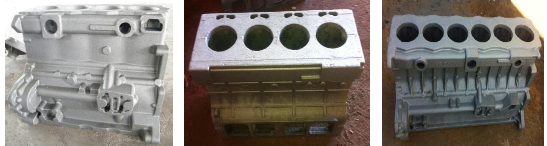
Typical engine cylinder blocks exhibit complex geometry with dimensional variations across different models:
| Model | Length (mm) | Width (mm) | Height (mm) | Bore Diameter (mm) | Mass (kg) |
|---|---|---|---|---|---|
| A | 1143 | 585 | 568 | 172 | 370 |
| B | 978 | 398 | 526 | 134 | 274 |
| C | 859 | 400 | 474 | 116 | 229 |
| D | 741 | 528 | 413 | 91 | 198 |
| E | 861 | 547 | 459 | 117 | 212 |
The critical challenge lies in developing a universal gripping solution that accommodates bore diameter variations from 91mm to 172mm while handling surface-treated HT250 cast iron components without surface damage.
2. Fixture Mechanism Design
The proposed robotic fixture employs an internal expansion mechanism with three primary components:
- Hydraulic actuation system with position feedback
- Quick-change clamping jaw modules
- Multi-sensor positioning system
The clamping force calculation for the heaviest engine cylinder block (Model A) determines hydraulic parameters:
$$F_c = \frac{\pi D^2 P \eta}{4}$$
Where:
$F_c$ = Required clamping force (N)
$D$ = Hydraulic cylinder diameter (m)
$P$ = System pressure (Pa)
$\eta$ = Mechanical efficiency (0.9)
For Model A with 370kg mass:
$$F_c = 3700N = \frac{\pi (0.25)^2 \times 10^7 \times 0.9}{4}$$
3. Modular Jaw Design
The quick-change jaw system features three interchangeable insert types:
| Jaw Set | Compatible Models | Upper Jaw Thickness (mm) | Lower Jaw Thickness (mm) |
|---|---|---|---|
| Type 1 | A | 45 | 40 |
| Type 2 | B, C, E | 45 | 35 |
| Type 3 | D | 40 | 35 |
Jaw inserts utilize Cr12MoV steel with HRC 58-62 hardness and micro-textured surface patterns for enhanced friction:
$$\mu = 0.25 \times \left(1 + \frac{A_p}{A_c}\right)$$
Where:
$\mu$ = Effective friction coefficient
$A_p$ = Patterned surface area (mm²)
$A_c$ = Contact area (mm²)
4. Hydraulic System Implementation
The closed-loop hydraulic system features:
- 25cm bore diameter cylinders
- Proportional directional valves
- Pilot-operated check valves for safety
- Filtration system with 10μm accuracy
Pressure maintenance during engine cylinder block transfer ensures:
$$P_m \geq \frac{4F_s}{\pi D^2} + \Delta P$$
Where:
$P_m$ = Minimum system pressure (Pa)
$F_s$ = Safety factor (1.5 × maximum load)
$\Delta P$ = Pressure loss (typically 0.5MPa)
5. Intelligent Positioning System
The vision-guided positioning system achieves ±0.2mm repeatability through:
- High-resolution CMOS cameras (5MP)
- Adaptive LED illumination
- 9-point calibration algorithm
Coordinate transformation between robot and engine cylinder block features:
$$T_{world}^{block} = T_{world}^{cam} \times T_{cam}^{feature} \times T_{feature}^{block}$$
Where:
$T_{world}^{block}$ = Engine cylinder block pose in world coordinates
$T_{world}^{cam}$ = Camera mounting position
$T_{cam}^{feature}$ = Feature recognition transform
$T_{feature}^{block}$ = Known feature geometry
6. Operational Performance
Field testing demonstrated significant improvements:
| Metric | Conventional Fixture | New Design | Improvement |
|---|---|---|---|
| Changeover Time | 30 minutes | 10 minutes | 66% reduction |
| Positioning Accuracy | ±1.5mm | ±0.5mm | 67% improvement |
| Maintenance Cost | $15,000/year | $8,500/year | 43% reduction |
The flexible fixture design enables mixed-line production of engine cylinder blocks with 100% successful grip rate in 10,000+ cycles, demonstrating exceptional reliability for automotive foundry applications.