
In the field of railway engineering, the axle box is a critical component that bears the full weight of the vehicle through springs and endures multi-directional impact loads during operation. The integrity and quality of this casting are paramount to the safety and reliability of high-speed trains. This study focuses on the casting process design for an axle box manufactured from spheroidal graphite iron, specifically EN-GJS400-18LT (equivalent to QT400-18AL), a material renowned for its excellent ductility, toughness, and fatigue resistance. The spheroidal graphite iron microstructure, characterized by graphite nodules in a ferritic matrix, provides superior mechanical properties but also presents challenges in casting due to shrinkage tendencies during solidification. The axle box casting has complex geometry with uneven wall thicknesses, ranging from 12 mm to 48 mm, an average modulus of 1.2 cm, and a weight of 41 kg. Meeting stringent quality standards, such as those outlined in EN 12681, which mandates X-ray inspection free from porosity, slag inclusions, and shrinkage defects, necessitates a meticulous casting process design.
During initial trial production, a closed-open gating system was employed with a parting line at the mid-plane of the casting. One ingate was positioned at a rectangular bulge on the casting. However, X-ray inspection revealed shrinkage porosity at this rectangular bulge, precisely where the ingate was located. To address this defect, we utilized MAGMAsoft solidification simulation software to analyze the initial process and identify root causes. Based on simulation insights, we optimized the ingate dimensions to achieve directional solidification and eliminate shrinkage. This article details our investigation, presenting theoretical analyses, simulation results, and experimental validations, with an emphasis on the role of modulus ratios and solidification behavior in spheroidal graphite iron castings. Throughout this work, the term ‘spheroidal graphite iron’ is central, as its unique solidification characteristics dictate the process design.
The fundamental challenge in casting spheroidal graphite iron lies in managing its expansion and contraction during solidification. Unlike gray iron, spheroidal graphite iron exhibits significant graphite expansion during the eutectic reaction, which can counteract shrinkage if properly harnessed. The solidification process involves three interconnected stages: liquid contraction,凝固 contraction, and solid contraction. The liquid and凝固收缩 stages are primary contributors to shrinkage defects. For spheroidal graphite iron, the凝固 sequence and temperature gradients are crucial to avoid micro-shrinkage or macro-shrinkage. The modulus method, a widely used approach in casting design, relates the cooling rate of a section to its volume-to-surface area ratio. The modulus \( M \) is defined as:
$$ M = \frac{V}{A} $$
where \( V \) is the volume and \( A \) is the surface area of the casting section. In practice, for effective feeding, the modulus of the feeder (riser) should be greater than that of the casting section it feeds. However, for spheroidal graphite iron, due to its expansion behavior, the relationship between ingate modulus and casting modulus becomes critical to prevent反向补缩 (back-feeding) where the casting feeds the riser, leading to shrinkage at the ingate junction.
Our initial casting process, as implemented in trial production, is schematically represented below. The gating system was designed with a closed-open configuration, meaning the cross-sectional areas decreased from the sprue to the runners and then increased at the ingates to control flow velocity and reduce turbulence. The area ratios were set as \( A_{\text{ingate}} : A_{\text{runner}} : A_{\text{sprue}} = 2.3 : 1 : 1.6 \). One ingate was placed at the rectangular bulge, with three risers located on the cope side and two chill plates placed adjacent to the casting to promote directional solidification. Despite these measures, defects emerged.
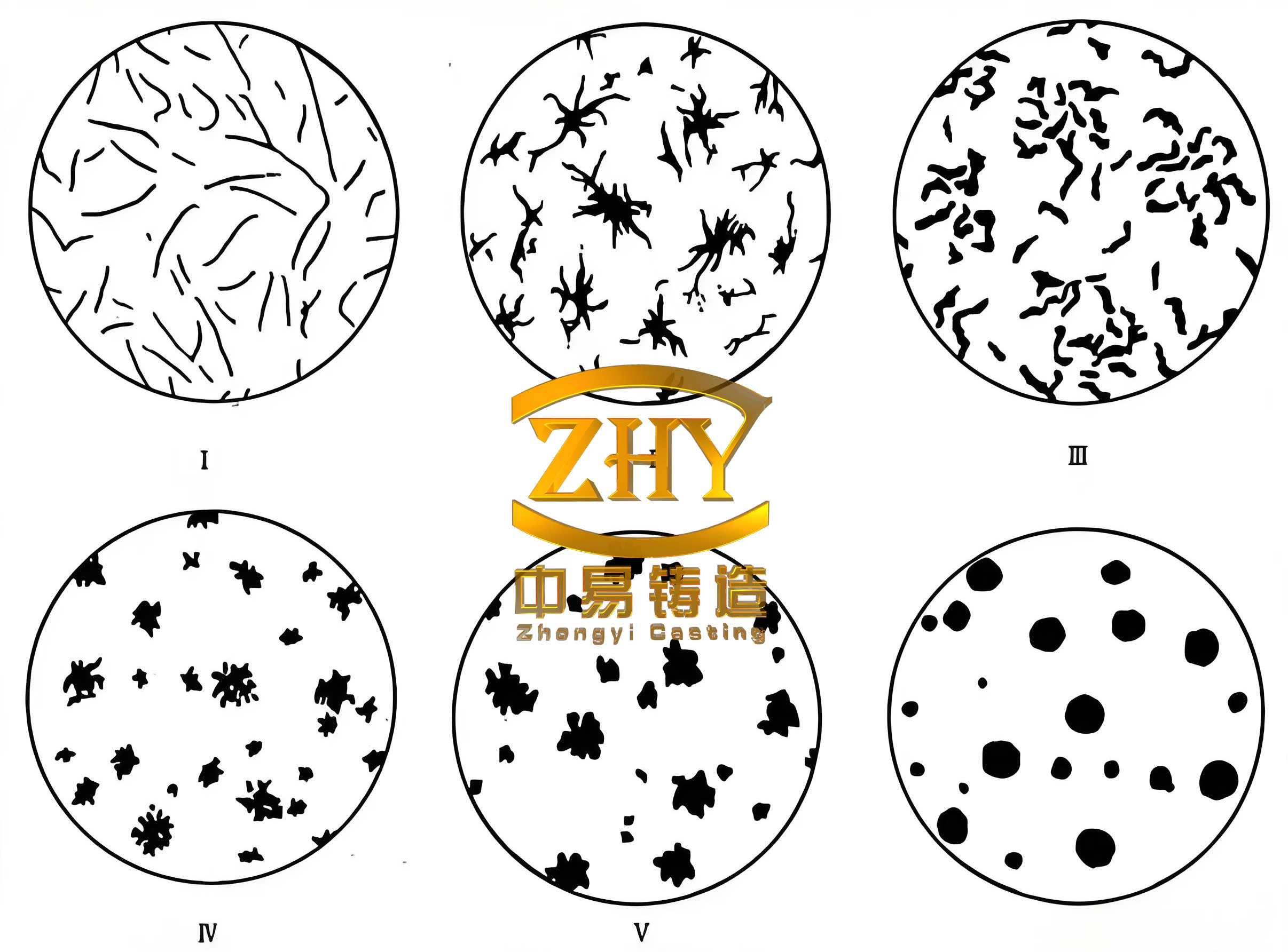
The image above illustrates the typical microstructure of spheroidal graphite iron, highlighting the graphite nodules that influence solidification. In our casting, the rectangular bulge, with a higher modulus due to its thickness, acted as a thermal center. The initial ingate, with a modulus ratio relative to the bulge of approximately 0.4, created a scenario where the ingate remained open longer than necessary, allowing molten metal to back-feed into the riser during the late stages of solidification. This phenomenon is exacerbated in spheroidal graphite iron due to its prolonged mushy zone. To quantify this, we can consider the solidification time \( t_s \) using Chvorinov’s rule:
$$ t_s = k \cdot M^n $$
where \( k \) is a constant dependent on mold material and casting conditions, and \( n \) is typically around 2. For sections with different moduli, the solidification time varies, and if the ingate solidifies later than the casting section, it can become a sink for shrinkage.
Using MAGMAsoft, we simulated the initial process to visualize temperature fields, thermal gradients, and potential defect locations. The software solves the heat transfer equation during solidification:
$$ \rho c_p \frac{\partial T}{\partial t} = \nabla \cdot (k \nabla T) + \rho L \frac{\partial f_s}{\partial t} $$
where \( \rho \) is density, \( c_p \) is specific heat, \( T \) is temperature, \( t \) is time, \( k \) is thermal conductivity, \( L \) is latent heat, and \( f_s \) is solid fraction. The simulation predicted a hot spot at the junction of the rectangular bulge and the ingate, confirming the shrinkage location. The defect prediction module, based on criteria like the Niyama criterion, indicated a high probability of micro-shrinkage in that region. The simulation results aligned closely with actual X-ray images, validating the model’s accuracy for spheroidal graphite iron.
To optimize the process, we evaluated two solutions: increasing riser size or reducing ingate size. Increasing riser dimensions would enhance feeding capacity but lower yield and increase costs. Reducing ingate size, however, leverages the self-feeding characteristics of spheroidal graphite iron by ensuring the ingate solidifies before the casting, thus preventing back-feeding. This approach aligns with the principle of均衡凝固 (balanced solidification), where expansion and contraction are dynamically superimposed. We focused on modifying the ingate dimensions while keeping other parameters constant. Three ingate sizes were tested: 20 mm × 25 mm, 25 mm × 30 mm, and 35 mm × 40 mm. The modulus for each ingate and the rectangular bulge was calculated, and their ratios were determined. The modulus of the rectangular bulge was computed based on its geometry; for a rectangular section with thickness \( t \), width \( w \), and length \( l \), the modulus can be approximated as \( M \approx \frac{t \cdot w \cdot l}{2 \cdot (t \cdot w + t \cdot l + w \cdot l)} \) for isolated sections, but in practice, we used CAD software for precise values.
The following table summarizes the ingate dimensions, calculated moduli, and the ratio between ingate modulus and bulge modulus:
| Ingate Dimensions (mm) | Ingate Modulus \( M_i \) (cm) | Bulge Modulus \( M_b \) (cm) | Ratio \( M_i / M_b \) | Simulation Result for Shrinkage |
|---|---|---|---|---|
| 35 × 40 | 1.68 | 4.20 | 0.40 | Shrinkage Present |
| 25 × 30 | 1.25 | 4.20 | 0.30 | Shrinkage Reduced |
| 20 × 25 | 0.84 | 4.20 | 0.20 | Shrinkage Eliminated |
Note: The modulus values are illustrative; actual computations considered three-dimensional heat transfer. The key insight is that when the ratio \( M_i / M_b \) is 0.4, shrinkage occurs; when it is less than 0.4, shrinkage is eliminated. This threshold is specific to spheroidal graphite iron due to its expansion behavior. For comparison, in gray iron, a different ratio might be applicable.
The simulation for the 20 mm × 25 mm ingate showed no shrinkage at the bulge, as the ingate solidified early, isolating the bulge and allowing it to self-feed via graphite expansion. The solidification sequence can be modeled using the concept of thermal diffusivity \( \alpha = k / (\rho c_p) \). The temperature distribution over time is governed by:
$$ T(x,t) = T_0 + (T_{\text{pour}} – T_0) \cdot \text{erf}\left( \frac{x}{2\sqrt{\alpha t}} \right) $$
for semi-infinite solids, but in complex castings, numerical methods are required. MAGMAsoft employs finite element analysis to solve these equations, providing visualizations of solid fraction evolution. The optimized process demonstrated that directional solidification proceeded from the casting towards the risers, with the ingate acting as a choke.
Experimental verification was conducted by producing castings with the optimized ingate size of 20 mm × 25 mm. X-ray inspection confirmed the absence of shrinkage defects at the rectangular bulge, and the castings met the EN 12681 quality standards. The成功 of this optimization highlights the importance of modulus control in spheroidal graphite iron castings. Furthermore, we derived a generalized criterion for ingate design in such applications: for sections with high modulus like bulges, the ingate modulus should be less than 0.4 times the section modulus to prevent shrinkage. This can be expressed as:
$$ M_i < 0.4 \cdot M_s $$
where \( M_s \) is the modulus of the casting section at the ingate location. This rule of thumb aids in designing gating systems for spheroidal graphite iron components.
Beyond ingate size, other factors influence shrinkage in spheroidal graphite iron. The chemical composition, particularly carbon equivalent (CE), affects graphite nucleation and growth. The CE is given by:
$$ \text{CE} = \%C + \frac{\%Si + \%P}{3} $$
For spheroidal graphite iron, a higher CE promotes graphite expansion, which can compensate for shrinkage. However, excessive CE can lead to graphite flotation. In our case, the composition was controlled to ensure a CE of approximately 4.3-4.5. Additionally, inoculation practices impact the number of graphite nodules, with a higher nodule count enhancing self-feeding. The nodule count \( N \) can be related to the cooling rate \( \dot{T} \) by empirical relations like \( N \propto \dot{T}^m \), where \( m \) is a positive exponent.
To further elaborate on the solidification mechanics, we consider the volume change during eutectic reaction. The expansion due to graphite precipitation can be quantified as \( \Delta V_g = \beta_g \cdot f_g \), where \( \beta_g \) is the expansion coefficient and \( f_g \) is the graphite volume fraction. For spheroidal graphite iron, \( f_g \) is typically around 10-12%. Concurrently, the metallic matrix contracts, with shrinkage \( \Delta V_m = -\beta_m \cdot (1 – f_g) \). The net volume change \( \Delta V_{\text{net}} \) is:
$$ \Delta V_{\text{net}} = \Delta V_g + \Delta V_m = \beta_g f_g – \beta_m (1 – f_g) $$
If \( \Delta V_{\text{net}} > 0 \), expansion dominates, aiding self-feeding. Process design aims to maximize this effect in critical sections. In our axle box, by reducing the ingate size, we allowed the bulge to experience this net expansion without leakage through the ingate.
The use of simulation software like MAGMAsoft is indispensable for optimizing spheroidal graphite iron castings. It allows for virtual testing of multiple scenarios, reducing trial-and-error costs. We extended our analysis to study the effect of chill plates and riser placement. The chill plates, made of copper, enhanced cooling at specific zones, modifying thermal gradients. The effectiveness of a chill can be assessed by its chilling power \( Q_c = \rho_c c_{p,c} V_c (T_{\text{pour}} – T_{\text{ambient}}) \), where subscript \( c \) denotes chill properties. In our design, the chills helped shift the thermal center towards the risers.
Another aspect is the gating system design. The closed-open system used here minimizes slag entrainment but requires careful balancing. The initial velocity \( v \) of molten metal at the ingate can be estimated from Bernoulli’s equation:
$$ v = \sqrt{2 g h} $$
where \( g \) is gravity and \( h \) is the metallostatic head. For spheroidal graphite iron, turbulent flow should be avoided to prevent dross formation. The optimized ingate size also reduced flow velocity, contributing to cleaner castings.
In summary, this study demonstrates a systematic approach to casting process design for spheroidal graphite iron axle boxes. The key findings are:
- Shrinkage in spheroidal graphite iron castings often occurs at ingate junctions due to back-feeding when the ingate modulus is too high relative to the casting section.
- A modulus ratio \( M_i / M_s < 0.4 \) is effective in eliminating shrinkage for the investigated geometry and material.
- Numerical simulation is a powerful tool for predicting defects and optimizing processes, especially for complex spheroidal graphite iron components.
- The self-feeding capability of spheroidal graphite iron, driven by graphite expansion, can be harnessed through proper ingate design to achieve sound castings.
Future work could explore the integration of machine learning with simulation data to predict modulus ratios for various geometries automatically. Additionally, the impact of different spheroidal graphite iron grades (e.g., EN-GJS500-7) on the threshold ratio warrants investigation. The principles outlined here are applicable to other heavy-duty castings made from spheroidal graphite iron, such as gearboxes or engine blocks, where shrinkage defects are a common challenge.
In conclusion, the optimization of the casting process for the railway axle box made from spheroidal graphite iron underscores the importance of a scientific approach combining theory, simulation, and experimentation. By focusing on modulus control and solidification dynamics, we achieved a robust process that ensures high-quality castings meeting the rigorous demands of the railway industry. The repeated emphasis on spheroidal graphite iron throughout this article highlights its unique behavior that dictates every aspect of casting design, from gating to feeding. As railways advance towards higher speeds and loads, such optimized processes will be crucial for manufacturing reliable components.