
As the lead designer for this ambitious project, I was tasked with developing a state-of-the-art foundry capable of producing 20,000 tons of high-quality machine tool castings annually. The core challenge was to leverage the client’s existing blast furnace infrastructure to create a highly efficient, short-process flow that minimizes energy consumption and environmental impact while maximizing output. This foundry specializes in large-scale machine tool bed castings, which are critical components in industrial machinery, requiring precise dimensional stability and superior mechanical properties. The entire design philosophy revolved around integrating advanced resin sand molding with direct hot metal charging from the blast furnace, a approach that sets a new benchmark for sustainable foundry operations.
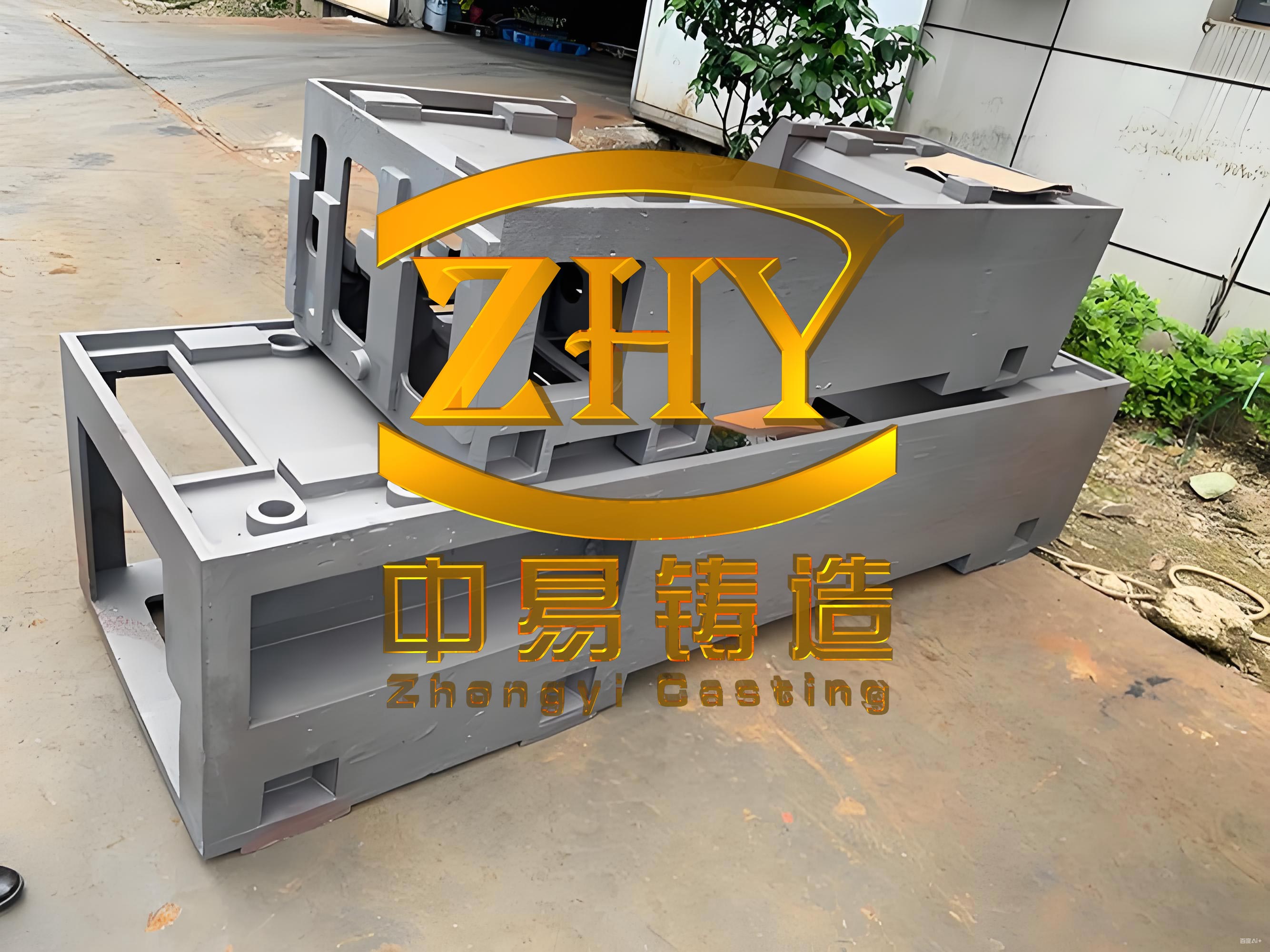
The production纲领 focuses exclusively on machine tool castings, primarily bed members and related components for presses and other heavy-duty equipment. The annual target of 20,000 tons encompasses a diverse range of sizes, with individual casting weights spanning from mere dozens of kilograms up to 8 tons. Among the flagship products are press bed castings with dimensions such as 3.5 m × 2.5 m × 1.0 m (8 tons), 2.8 m × 1.8 m × 0.9 m (5 tons), and 2.0 m × 1.5 m × 0.8 m (3 tons). The material breakdown is predominantly gray iron, supplemented by smaller volumes of ductile iron and alloyed iron to meet specific performance criteria for different machine tool applications. This variety necessitates a flexible and robust manufacturing system capable of handling these substantial machine tool castings without compromising on quality or efficiency.
The heart of the melting department is the innovative short-process system that directly utilizes molten iron from the existing 318 m³ and 179 m³ blast furnaces. The blast furnace operates on a tapping schedule of 8 tons every 2 hours, with a typical tapping temperature of approximately 1,350 °C. This hot metal is transported via rail-bound electric transfer cars and charged directly into medium-frequency coreless induction furnaces for superheating and composition adjustment. The primary objective is to elevate the temperature to 1,550 °C for optimal pouring conditions and effective metallurgical treatment. The process demands that the entire cycle—from charging 8 tons of hot metal into the furnace to tapping—must be completed within a strict 2-hour window to synchronize with the blast furnace rhythm. A key feature of this setup is the use of two 6-ton furnace bodies powered by a dual-supply, parallel resonance intermediate frequency system. This configuration includes one 2,400 kVA transformer, two 1,350 kW IF power supplies, and two 6-ton furnace bodies interconnected via a power distributor. The system operates with a total power draw not exceeding 2,100 kW, allowing one furnace to function at full melting power while the other maintains a holding or lower-power melting state. This ensures a continuous and flexible supply of molten iron, crucial for producing large machine tool castings.
The melting capacity was rigorously calculated to verify it meets the production targets. For a 6-ton furnace with a melting cycle of 1 hour, operating 20 effective hours per day over 300 working days per year, the annual melting capacity is given by:
$$ \text{Annual Melted Iron} = \left( \frac{6 \, \text{tons}}{\text{cycle}} \times 20 \, \frac{\text{cycles}}{\text{day}} \right) \times 300 \, \text{days} = 36,000 \, \text{tons} $$
Factoring in a casting yield of 70% and a product合格率 of 90%, the annual output of sound machine tool castings is:
$$ \text{Annual Sound Castings} = 36,000 \times 0.70 \times 0.90 = 22,680 \, \text{tons} $$
This comfortably exceeds the 20,000-ton target, providing a healthy operational buffer. Charging of cold charge materials (scrap steel, returns) is handled by a 5-ton overhead crane equipped with a 1-ton electromagnetic chuck, while hot metal handling employs a 16-ton twin-hook冶金 crane, a 10-ton holding ladle, and a 20-ton electronic weighing system for automated and precise charge control. Molten metal quality is monitored using a front-of-furnace rapid thermal analyzer, a direct-reading optical emission spectrometer for composition checks, and electronic thermocouple lances for temperature verification before tapping for the machine tool castings.
The molding and coremaking department is entirely based on the furan resin cold-box process, selected for its excellent dimensional accuracy and surface finish, which are paramount for precision machine tool castings. To accommodate the wide size range of these castings, multiple continuous mixers with different capacities are deployed: one 30 t/h mobile mixer for large molds, one 20 t/h and one 15 t/h stationary mixer for medium-sized work, and one 10 t/h stationary mixer dedicated to the coremaking area. This stratification ensures efficient resin sand preparation tailored to the specific demands of each machine tool casting type. A 2.5-ton gantry crane is installed in the molding bay to facilitate precise core setting, enhancing internal dimensional accuracy of the castings. Cores are coated with alcohol-based coatings applied manually via spray guns, supported by pillar-mounted jib cranes for easy handling and rotation. A through-type gas-fired drying oven is integrated into the core shop to ensure proper drying of coated cores.
The calculation for the total annual resin sand requirement is critical for sizing the mixing equipment. It is derived from the production纲领, considering sand-to-metal ratio, rejection rates, and sand losses:
$$ Q = C \times S \times (1 + \alpha) \times (1 + \beta) \times (1 + \gamma) $$
Where:
$C$ = Production target (using $C_1 = 20,000$ tons and $C_2 = 22,680$ tons for capacity analysis)
$S$ = Average sand-to-metal ratio (taken as 3:1)
$\alpha$ = Casting scrap rate (3% or 0.03)
$\beta$ = Mold scrap rate (2% or 0.02)
$\gamma$ = Sand loss rate (5% or 0.05)
Thus, for the 20,000-ton target:
$$ Q_1 = 20,000 \times 3 \times (1 + 0.03) \times (1 + 0.02) \times (1 + 0.05) = 66,188 \, \text{tons/year} $$
And for the 22,680-ton melted capacity:
$$ Q_2 = 22,680 \times 3 \times (1.03) \times (1.02) \times (1.05) = 75,057 \, \text{tons/year} $$
With 300 working days and an effective daily mixing time of 10 hours, the daily sand requirement ranges from 220 to 250 tons. The hourly demand $P_h$ is therefore 22 to 25 t/h. The total installed mixer capacity $P_m$ is 75 t/h (30+20+15+10), resulting in a load factor $\eta$ of approximately 30%, which is within the typical operating range of 30-40% for such equipment. However, a critical check against the resin sand’s usable life (pot life) is necessary. For a large mold requiring 12 tons of sand (e.g., for an 8-ton machine tool bed) and a maximum usable time $T_{\text{max}}$ of 12 minutes (0.2 hours), the required instantaneous mixing rate would be:
$$ \frac{W_{\text{max}}}{T_{\text{max}}} = \frac{12}{0.2} = 60 \, \text{t/h} $$
This exceeds the 30 t/h capacity of the largest mobile mixer. To address this, the process allows for filling areas away from the pattern with plain recycled sand, and the 30 t/h unit was selected as a practical compromise considering capital investment constraints.
| Mixer Type | Capacity (t/h) | Primary Application | Location/Feature |
|---|---|---|---|
| Mobile | 30 | Large machine tool casting molds | Main molding bay, serves pouring pits |
| Stationary | 20 | Medium-sized machine tool casting molds | Main molding bay |
| Stationary | 15 | Small to medium machine tool casting molds | Secondary molding bay |
| Stationary | 10 | Coremaking for all machine tool castings | Coremaking area |
The sand reclamation department is a cornerstone of the foundry’s economic and environmental strategy, aiming to minimize new sand consumption and waste disposal. A 25 t/h capacity resin sand reclamation system was selected. The required capacity was calculated based on the annual sand demand, reclamation rate, an imbalance factor, and the annual equipment operating hours. The annual equipment time base $T$ for 10 hours/day and 300 days, with a 5% downtime allowance $(\delta=0.05)$, is:
$$ T = 10 \times (1 – 0.05) \times 300 = 2,850 \, \text{hours} $$
The reclamation system capacity $P$ is then:
$$ P = \frac{Q \Psi K}{T} $$
Where:
$Q$ = Annual sand volume (using $Q_1=66,188$ tons for a conservative estimate)
$\Psi$ = Sand reclamation rate (95% or 0.95)
$K$ = Imbalance factor (1.2)
$$ P = \frac{66,188 \times 0.95 \times 1.2}{2,850} \approx 25.37 \, \text{t/h} $$
A 25 t/h system was therefore chosen. The reclaimed sand must meet stringent quality standards to be suitable for producing high-integrity machine tool castings, including a LOI (Loss on Ignition) ≤ 2%, micro-fines content ≤ 0.3%, and temperature ≤ 35°C after cooling.
The sand reclamation process flow is meticulously designed: Used sand from shakeouts → Vibrating conveyor → Overhead magnetic separator → 1st bucket elevator → 1st storage silo → Vibrating feeder → Vibrating crusher → 2nd bucket elevator → 2nd storage silo → Fluidized bed cooler → 3rd bucket elevator → Magnetic separator → Reclamation unit (mechanical or thermal) → 4th bucket elevator → 3rd storage silo → Sand temperature regulator → 5th bucket elevator → 4th dual-chamber storage silo → Pneumatic transport sender → Finished sand silos above mixers → Sand proportional feeder → Mixers for molding. The binder addition for furan resin is optimized based on sand composition: 1.1-1.5% for 100% new sand, and 0.8-1.1% for blends with ≤20% new sand or 100% reclaimed sand. The system requires substantial utilities: cooling water at 8-10 m³/h and compressed air at 30 Nm³/min, pressure ≥0.75 MPa.
| Parameter | Target Specification |
|---|---|
| Reclamation Capacity | ≥ 25 t/h |
| Sand Recovery Rate | ≥ 95% |
| Resin Film Removal Rate | ≥ 22% (Supplier claim: ≥ 28%) |
| Reclaimed Sand LOI | ≤ 2% |
| Reclaimed Sand Micro-fines | ≤ 0.3% |
| Reclaimed Sand Temperature | ≤ 35 °C |
| Dust Collector Efficiency | ≥ 99% |
| Dust Emission Concentration | ≤ 100 mg/m³ |
| Mixing Uniformity Error | ≤ ±3% |
| Liquid Binder Dosing Accuracy | ≤ ±1.5% |
Castings shakeout is performed using two units: a 30-ton (2×15 ton modular) vibrating grid and a 10-ton vibrating grid, chosen to handle the weight range of the machine tool castings. The hot sand is conveyed away via vibrating conveyors and chain-type bucket elevators. The cleaning and heat treatment department is vital for delivering finished machine tool castings. After shakeout, castings are transported on 15-ton electric transfer cars to the core knockout station, then to the cleaning bay for removal of gates and risers. A combination of cleaning equipment is used: a long-chamber hook-type shot blaster for smaller or elongated components, a table-type shot blasting machine for heavy, bulky machine tool castings, and a continuous through-type shot blasting machine for long castings. Following shot blasting, castings undergo stress relief annealing in a gas-fired furnace to ensure dimensional stability, a critical step for all machine tool castings. Final operations include grinding, fettling, inspection, layout marking, and painting before dispatch.
The overall foundry workflow can be summarized in the following block diagram, illustrating the integrated short-process flow from molten metal to finished machine tool castings:
Process Flow: Blast Furnace Hot Metal → Transport → Medium Frequency Furnace (Heating/Adjustment) → Molten Iron Analysis → Pouring → Molding (Resin Sand) → Coremaking → Mold Assembly → Cooling → Shakeout → Casting Transfer → Core Knockout → Gate/Riser Removal → Shot Blasting → Heat Treatment (Stress Relief) → Finishing (Grinding, etc.) → Inspection → Painting → Finished Machine Tool Castings Storage.
Major equipment selection was driven by the specific requirements of producing heavy-section machine tool castings. The melting section centers on the 6-ton IF furnace system with dedicated closed-circuit cooling towers (50 t/h for power supply, 150 t/h for furnace bodies). The sand preparation and reclamation line is built around the 25 t/h system. The cleaning section features two shot blasting machines (10-ton and 5-ton capacity) and the gas-fired stress relief furnace. Material handling relies on a fleet of overhead cranes: four QDY double-girder冶金 cranes, three LDY single-girder冶金 cranes, and two LD standard single-girder cranes, supplemented by electric transfer cars (one 20-ton and two 15-ton units).
The workshop layout is a four-bay, light steel structure with color steel plate cladding, spanning a total length of 108.8 meters and a maximum width of 69 meters (across four bays), with a total floor area of 6,258 m². The layout is logically zoned to separate molding/cleaning and optimize material flow for these sizable machine tool castings. Bay 1 (21.5 m wide) houses large-part molding, coremaking, and assembly, served by 32/10/10-ton cranes. Bay 2 (9.5 m wide) contains the IF furnace system, charge preparation, sand reclamation, and laboratory facilities, served by 16/5-ton cranes. Bay 3 (24 m wide) is dedicated to smaller castings molding and coremaking, served by 10-ton cranes. Bay 4 (15 m wide, 30.5 m long) is the cleaning and finishing bay, equipped with shot blasters and the heat treatment furnace, served by a 10-ton crane. Ancillary spaces like the substation, offices, and compressor room are strategically placed within the structure.
The utility design was meticulously planned to support the massive scale of operations required for 20,000 tons of machine tool castings. Water supply encompasses domestic use (35 L/person/shift, peak flow 3.3 m³/h), production process cooling (200 m³/h for furnaces, 100 m³/h for sand cooling, both recirculating with a total makeup of 10.8 m³/h), and firefighting (indoor 10 L/s, outdoor 20 L/s, requiring a total of 216 m³ for a 2-hour reserve). Heating is only provided for office spaces, while the main workshop relies on roof-mounted natural draft ventilators and large windows for climate control. The compressed air system, powered by two screw compressors (130 kW total), delivers 30 Nm³/min at 0.75 MPa. The electrical load is substantial, dominated by the IF furnace (2,100 kW). The power distribution involves a main substation with a dedicated 2,400 kVA transformer for the furnaces and two 560 kVA oil-immersed transformers for the remaining plant load (sand system ~516 kW, cranes ~285 kW, shot blasting ~100 kW, auxiliaries ~50 kW).
Energy conservation, environmental protection, safety, and industrial hygiene were paramount throughout the design process. The building envelope itself is a key节能 feature, using light steel panels with rock wool insulation for excellent thermal performance. Roof light bands provide ample natural illumination, reducing lighting energy needs. The most significant节能 achievement is the sand reclamation system, achieving a 95% recycle rate, drastically reducing virgin sand use and waste sand disposal associated with producing machine tool castings. The IF furnace cooling system uses closed-loop circuits, minimizing water consumption.
Environmental controls are comprehensive. Fugitive emissions from the IF furnaces (dust concentration 300-800 mg/m³) are captured by movable hoods and treated by baghouse filters before emission from stacks, achieving outlet concentrations ≤100 mg/m³. Similarly, dust from shakeouts and shot blasting (500-1,000 mg/m³) is captured at source and cleaned via dedicated baghouse collectors. Noise pollution from sources like fans and shot blasting machines is mitigated using vibration isolators, silencers, and acoustic enclosures, maintaining workshop noise levels below 85 dB(A).
Fire safety is addressed by classifying the workshop as a Class D/E fire hazard and designing the steel structure with fire-resistant coatings to achieve a 2-hour fire rating. Adequate escape routes, fire hydrants (10 L/s indoor, 20 L/s outdoor), and sufficient water storage (80 m³ underground, 1,000 m³ elevated) are incorporated. Worker safety protocols include mandatory Personal Protective Equipment (PPE) like heat-resistant suits and face shields for furnace operations, emergency stop buttons on all major equipment, proper machine guarding, electrical grounding (resistance ≤4 Ω), and audible alarms on cranes. Platforms above 2 meters are fitted with 1.05-meter high guardrails. The design ensures dust concentrations remain below the 10 mg/m³ threshold limit value for worker呼吸 protection.
In conclusion, the successful commissioning and trial operation of this foundry validate the design principles. The integration of the short-process molten metal supply with advanced resin sand technology and comprehensive sand reclamation has resulted in a facility that not only meets its production target for high-quality machine tool castings but does so with remarkable economic, environmental, and energy efficiency. This project serves as a compelling model for modern, sustainable foundry operations, particularly specialized in the demanding field of machine tool castings production. The lessons learned here, especially in optimizing material and energy flows for large-scale components, are widely applicable to the future of metal casting industries.