1. Introduction
The casting process of ductile iron differential cases is a crucial aspect in the manufacturing of automotive components. This article focuses on the development and optimization of the casting process for a specific ductile iron differential case, aiming to achieve high-quality products with minimal defects and efficient production.
1.1 Background
In the automotive industry, differential cases play a vital role in the drivetrain system. The demand for high-performance and reliable differential cases has led to continuous research and development in casting techniques. Ductile iron, with its excellent mechanical properties, is a preferred material for differential cases. However, achieving the desired quality and productivity requires a well-designed casting process.
1.2 Objectives
The main objectives of this study are:
- To develop a casting process that meets the technical requirements of the differential case, including dimensional accuracy, mechanical properties, and defect-free casting.
- To optimize the process to improve production efficiency, reduce costs, and increase the yield rate.
2. Technical Requirements of the Differential Case
2.1 Design Specifications
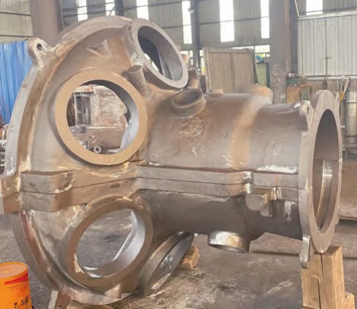
The differential case has a unique design with specific features such as multiple windows and pin holes. The design details are as follows:
| Feature | Specification |
|---|---|
| Windows | 4 windows |
| Pin Holes | 3 pin holes |
| Flange Design | 3 non-symmetric bosses on the flange face |
| Diameter | ϕ161 mm |
| Flange Thickness | 8.3 mm |
| Weight | 3.32 kg (毛坯), 2.32 kg (成品) |
2.2 Material Requirements
The material used for the differential case is QT600 – M (enterprise standard). The chemical composition and mechanical properties are as follows:
| Element | Composition Range |
|---|---|
| C | 3.3 – 3.9 |
| S | ≤0.02 |
| Si | 1.8 – 3.0 |
| Mn | 0.2 – 1.0 |
| P | ≤0.06 |
| Cu | 0.2 – 1.0 |
| Ti | ≤0.06 |
| Sn | ≤0.06 |
| Mg | 0.027 – 0.06 |
| Mechanical Property | Requirement |
|---|---|
| Tensile Strength | 650 MPa |
| Yield Strength | ≥405 MPa |
| Elongation | 3% |
| Hardness (HBW) | 200 – 265 |
| Spheroidization Rate | 80% |
| Graphite Type | V + VI |
| Pearlite | 55% |
| Carbides and Phosphorus Eutectic | 3% |
2.3 Dimensional Tolerance and Defect Requirements
The dimensional tolerance and defect requirements for the casting are as follows:
| Aspect | Requirement |
|---|---|
| Dimensional Tolerance | ISO8062 – CT9 |
| Contour Tolerance | 2(±1) mm |
| External Defects | Key machining surfaces: diameter ≤ 1mm, depth ≤ 1mm; Non-key machining surfaces: diameter ≤ 3mm, depth ≤ 1mm; Blank surfaces: diameter ≤ 4mm, depth ≤ 1mm (visible holes) |
| Internal Defects | Porosity meets D3/1; X-ray inspection meets ASTM E – 446 ≤ level2 |
3. Initial Process Design
3.1 Double Riser Scheme
Based on the characteristics of the differential case, a double riser scheme was initially designed. Two risers were placed at the flange positions corresponding to two of the pin holes. The design details of the risers are as follows:
| Riser Type | Dimensions (mm) | Weight (kg) | Modulus (mm) |
|---|---|---|---|
| Single-use Riser (side) | 120 × 43 × 50 | 2.1 | 6 |
| Common Riser (middle) | 120 × 55 × 50 | – | – |
The riser neck was designed with a height of 7.7 mm, a length of 55 mm, and an area of 423 . The top of the riser had a 15 mm de-weighting pressure groove, and the bottom had a 15 mm separation block.
3.2 Gating System Design
The gating system was designed using a lap joint method. The vertical and horizontal runners were lapped once, and the vertical runners were further lapped through 6 mm thin sheets. The final ingate was lapped with the vertical runner again. The ingate entered the iron from the bottom of the riser to reduce the impact of the iron liquid flow on the sand mold and prevent impurities from entering the casting cavity.
3.3 Shrinkage Compensation Measures
- Axis Head Filling: For the isolated hot spot at the axis head position, 60% of the axis head height (29 mm out of 48 mm) was filled to meet the D3/1 defect requirement for shrinkage porosity. The inner cavity of the axis head was partly formed by an outer mold with an inner diameter of ϕ39 mm and a 14 mm outer mold formation at the corresponding position. The draft angle was 15°.
- Flange Thickness Subsidy: A 0.5 mm thickness subsidy was provided at the flange position corresponding to the riser to compensate for shrinkage.
- Cold Needle Setting: A cold needle (ϕ6 mm × 25 mm) with a 3° draft angle was set at the pin hole position.
4. Simulation and Optimization of the Process
4.1 Simulation Results and Analysis
The simulation of shrinkage porosity and other defects was carried out. The initial simulation results showed shrinkage porosity at the pin hole and flange positions. The sizes of the shrinkage pores at the pin hole position were 2.6 and 11.0 , and at the flange position was 0.7 .
4.2 Process Adjustment
To address the issues identified in the simulation, the following adjustments were made:
- Rotation of the Casting: The casting was rotated 90°. After rotation, two of the three bosses were closer to the riser position, and the riser was no longer directly opposite the pin hole but opposite the window. The cold needle was cancelled. The adjusted simulation results showed no shrinkage porosity at the pin hole position, and the shrinkage porosity at the axis head position was within a machinable range (77.8 – 80.00 mm).
- Exhaust System Improvement: In the sample trial production, it was found that the pouring time was long and unstable due to gas generated during the pouring process from the large sand core. To solve this problem, exhaust sheets were added to the horizontal runner, and the bottom of the exhaust sheet was made into a separation block.
- Gating System Optimization: To improve the yield rate, two vertical runners were cancelled, and the horizontal runner was weight-reduced. The ingate directly entered the iron from the top of the riser and was lapped with the inner runner of the riser. These optimizations shortened the pouring time from 13 – 16 s to 10.2 – 10.3 s and increased the process yield rate from 36.7% to 42.7%.
5. Sample Trial Production and Quality Inspection
5.1 Trial Production Process
Samples were produced using the adjusted process. The pouring process was carefully monitored, and the quality of the samples was inspected at various stages.
5.2 Quality Inspection Results
- External Quality: The appearance and dimensions of the samples were all qualified.
- Internal Quality: 100% X-ray inspection showed no internal defects, and the porosity and other properties met the requirements. The client’s third-party CT inspection also confirmed the quality of the samples.
6. Mass Production and Quality Control
6.1 Mass Production Process
After successful sample trial production, mass production was carried out. The production process was strictly controlled to ensure consistent quality.
6.2 Quality Control Measures
- In-process Inspection: Regular inspections were carried out during the production process to monitor the quality of the castings. Any defects or deviations were immediately addressed.
- Final Inspection: After production, a comprehensive final inspection was carried out on each casting. The inspection items included appearance, dimensions, mechanical properties, and internal defects.
6.3 Production Results and Quality Statistics
In a certain month of mass production, 1887 pieces were inspected for appearance. Among them, 62 pieces were defective, with a qualification rate of 96.71%. The specific defect types and rates were as follows:
| Defect Type | Number of Defects | Defect Rate |
|---|---|---|
| Sand Holes in Appearance | 37 | 1.96% |
| Impact Damage | 18 | 0.95% |
| Unclear Casting Characters after Shot Blasting | 7 | 0.37% |
| Processing Defects at the Client End | < 1% | – |
7. Conclusion
The development and optimization of the casting process for the ductile iron differential case have achieved satisfactory results. The process meets the technical requirements of the differential case, with high-quality products and efficient production. The following are the key achievements:
- A suitable casting process was developed, including a double riser scheme and a lap joint gating system, which effectively compensated for shrinkage and ensured the quality of the casting.
- Through simulation and optimization, the process was continuously improved. The pouring time was shortened, and the process yield rate was increased.
- The samples and mass-produced products passed various quality inspections, with a high qualification rate in mass production, meeting the product development goals.
In the future, further research can be carried out to explore more advanced casting techniques and improve the performance and quality of the differential case. This study provides a valuable reference for the casting industry in the production of ductile iron differential cases.
8. Importance of Casting Process Optimization
8.1 Cost Reduction
Optimizing the casting process can lead to significant cost reductions. By improving the yield rate, less material is wasted, which directly reduces the material cost. For example, in the case of the ductile iron differential case, increasing the process yield rate from 36.7% to 42.7% means that more usable castings are produced from the same amount of raw materials. This not only saves on the cost of the ductile iron but also reduces the cost associated with handling and disposing of waste materials.
8.2 Quality Improvement
A well-optimized casting process ensures better quality of the final product. This is crucial for components like differential cases that are integral to the performance and safety of a vehicle. By minimizing defects such as shrinkage porosity and ensuring accurate dimensional tolerances, the reliability and durability of the differential case are enhanced. In turn, this reduces the likelihood of failures in the drivetrain system, leading to improved vehicle performance and fewer maintenance requirements.
8.3 Increased Productivity
Shorter pouring times and more efficient processes allow for increased productivity. In a manufacturing environment, time is a valuable resource. By reducing the pouring time from 13 – 16 s to 10.2 – 10.3 s, as in the case of our differential case casting process, more castings can be produced in a given time period. This enables manufacturers to meet higher production demands and potentially gain a competitive edge in the market.
9. Challenges and Solutions in Casting Process Development
9.1 Gas Generation and Venting
One of the major challenges faced during the casting process was the generation of gas from the large sand core during pouring. This gas affected the pouring time and could potentially lead to defects in the casting. The solution was to add exhaust sheets to the horizontal runner and make the bottom of the exhaust sheet into a separation block. This allowed for efficient venting of the gas, improving the pouring process and reducing the likelihood of defects.
9.2 Shrinkage Compensation
Compensating for shrinkage was another critical challenge. The differential case had specific areas prone to shrinkage, such as the axis head and flange positions. To address this, a combination of measures was employed. These included filling a portion of the axis head, providing a thickness subsidy at the flange, and setting a cold needle at the pin hole position. Through continuous simulation and adjustment, an effective shrinkage compensation strategy was developed.
9.3 Dimensional Accuracy
Ensuring dimensional accuracy was essential for the proper functioning of the differential case. The complex design of the case, with multiple windows and pin holes, made it difficult to achieve precise dimensions. However, by carefully designing the casting process, including the riser and gating system, and closely monitoring the production process, the required dimensional accuracy was achieved. Regular inspections and adjustments were made to maintain the correct dimensions throughout the production process.
10. Future Trends in Casting Technology for Differential Cases
10.1 Advanced Simulation Techniques
As computing power continues to increase, more advanced simulation techniques will be available for casting process development. These simulations will be able to provide more detailed and accurate predictions of the casting process, allowing for better optimization before actual production. For example, simulations could model the flow of the molten metal in greater detail, taking into account factors such as turbulence and heat transfer, to further improve the design of the gating system and risers.
10.2 Use of New Materials
The search for better materials for differential cases will continue. While ductile iron has proven to be a suitable material, research may lead to the discovery of new alloys or composites that offer even better mechanical properties and performance. These new materials could potentially improve the strength, durability, and weight of the differential case, contributing to overall vehicle performance and fuel efficiency.
10.3 Automation and Industry 4.0 Integration
The casting industry is increasingly moving towards automation and integration with Industry 4.0 concepts. In the context of differential case casting, this could involve the use of automated pouring systems, robotic handling of castings, and real-time monitoring and control of the casting process using sensors and data analytics. Automation can improve productivity, reduce human error, and ensure more consistent quality in the production of differential cases.
11. Case Studies of Similar Casting Processes
11.1 Another Ductile Iron Component
In a similar study of a different ductile iron component, a comparable approach was used to optimize the casting process. The component had its own set of design requirements and challenges, but many of the principles applied in our differential case study were relevant. By using a combination of proper riser design, gating system optimization, and defect control measures, a successful casting process was developed, resulting in a high-quality product with good yield rates and minimal defects.
11.2 A Casting Process for a Related Automotive Component
Another case study involved a casting process for a related automotive component. This component had different mechanical and dimensional requirements, but the overall goal of achieving a reliable and efficient casting process was the same. Through careful analysis of the component’s characteristics and the application of appropriate casting techniques, such as shrinkage compensation and gas venting, a viable casting process was established, meeting the industry standards and requirements for the component.
12. Conclusion
The development and optimization of the casting process for ductile iron differential cases is a complex but rewarding endeavor. It involves addressing various challenges such as gas generation, shrinkage compensation, and dimensional accuracy to achieve a high-quality product with efficient production. Through continuous improvement and the application of advanced techniques, the casting process can be further enhanced in the future. The importance of this process cannot be overstated, as it directly impacts the performance and safety of vehicles. Looking ahead, trends such as advanced simulation techniques, new materials, and automation offer exciting opportunities for further development in the casting of differential cases. By learning from case studies of similar processes and staying updated with the latest industry trends, manufacturers can continue to improve their casting processes and produce superior differential cases for the automotive industry.